An anti-off protection mechanism for furniture sliding doors

A technology for protection mechanisms and sliding doors, which is applied in the direction of windows/doors, building components, door/window accessories, etc. It can solve problems such as inconvenient installation, inconvenient disassembly of the door body, shaking, etc., and achieves convenient installation, smooth and stable sliding and pulling , the effect of simple structure

Active Publication Date: 2020-11-17
SHAOYANG UNIV
View PDF8 Cites 0 Cited by
  • Summary
  • Abstract
  • Description
  • Claims
  • Application Information

AI Technical Summary

Problems solved by technology

[0003] The traditional sliding door is not conducive to the assembly of the door body. In order to facilitate the assembly, most of the traditional sliding doors leave a large gap between the door and the door frame, so that the rollers on the door can cooperate with the guide rails of the door frame. This design is easy to make the door The body will fall during use, causing damage to the door body and the user's body injury. The door of this design will shake more seriously due to the large gap when pushing and pulling, which is not conducive to improving the quality of the sliding door.
[0004] Some traditional sliding doors with anti-off function often need post-installation limiters, and the installation of limiters requires the use of screws and other parts, which is inconvenient to install and subsequent disassembly of the door body is also inconvenient

Method used


Image

  • An anti-off protection mechanism for furniture sliding doors
  • An anti-off protection mechanism for furniture sliding doors
  • An anti-off protection mechanism for furniture sliding doors

Examples


Embodiment Construction

[0016] In order to make the purpose, technical solutions and advantages of the embodiments of the present invention clearer, the technical solutions in the embodiments of the present invention will be clearly and completely described below in conjunction with the drawings in the embodiments of the present invention. Obviously, the described embodiments It is a part of embodiments of the present invention, but not all embodiments. Based on the embodiments of the present invention, all other embodiments obtained by persons of ordinary skill in the art without creative efforts fall within the protection scope of the present invention.

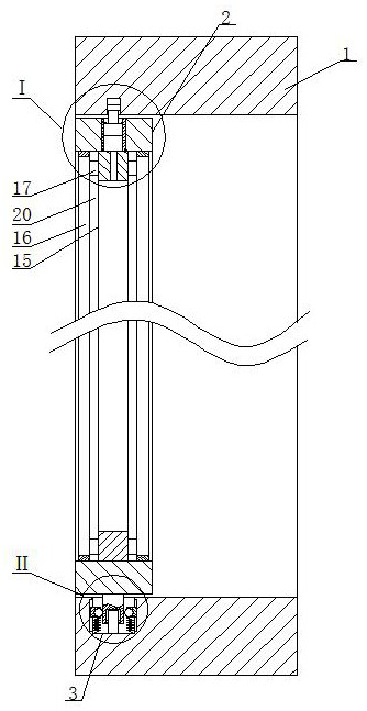
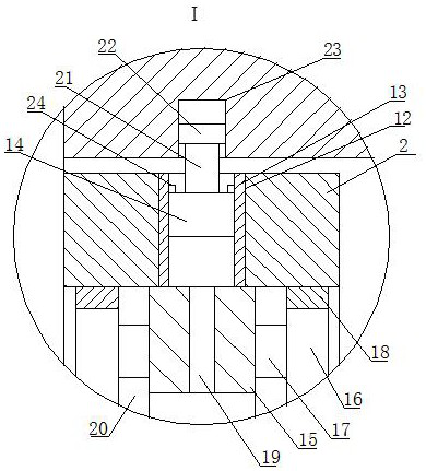
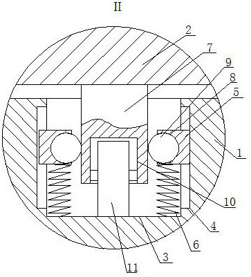
[0017] An anti-off protection mechanism for furniture sliding doors, as shown in the figure, includes an installation frame 1, a door frame 2 is arranged inside the installation frame 1, and a first long groove is opened on the inner bottom surface of the installation frame 1 corresponding to the lower end of the door frame 2 3. There are several ...


PUM


Abstract

The invention discloses an anti-separation protection mechanism of a furniture sliding door. The anti-separation protection mechanism comprises a mounting frame, wherein a door frame is arranged in the mounting frame, a first long-strip-shaped groove is formed in the position, corresponding to the lower end of the door frame, of the bottom surface in the mounting frame, a plurality of sliding grooves which are uniformly distributed in the front-back direction are formed in the left side surface and the right side surface of the first long-strip-shaped groove and are vertical, sliding blocks are arranged in the sliding grooves in a matched mode, and the lower ends of the sliding blocks are fixedly connected with the inner bottom of the first long-strip-shaped groove through springs; an inserting plate is fixedly arranged at the bottom of the door frame, the inserting plate is inserted into the first long-strip-shaped groove, hemispherical grooves are formed in the end face, facing the inserting plate, of the sliding blocks, ball bodies are arranged in the hemispherical grooves in a matched mode, and the ball bodies are in contact fit with the corresponding side face of the inserting plate. The anti-separation protection mechanism is simple in structure, the door frame cannot automatically fall off, the sliding door is smooth and stable when pushed and pulled, two people can conveniently dismount the door frame through a sucker tool and also can conveniently mount the door frame, but one person can hardly dismount the door frame, even if the door frame is collided mistakenly, the door frame cannot fall off, and the door frame is convenient to use and install and stable.

Description

technical field [0001] The invention belongs to the technical field of anti-off sliding doors, in particular to an anti-off protection mechanism for sliding doors of furniture. Background technique [0002] A sliding door is a commonly used door in the home, which refers to a door that can be pushed and pulled. With the development of technology and the diversification of decoration methods, sliding doors have changed from traditional plate surfaces to glass, fabric, rattan, aluminum alloy profiles, from sliding doors, folding doors to partition doors, and the functions and scope of use of sliding doors are constantly changing. expand. [0003] The traditional sliding door is not conducive to the assembly of the door body. In order to facilitate the assembly, most of the traditional sliding doors leave a large gap between the door and the door frame, so that the rollers on the door can cooperate with the guide rails of the door frame. This design is easy to make the door T...

Claims


Application Information

Patent Timeline
Patent Type & Authority Patents(China)
IPC IPC(8): E05D13/00E05D15/06E06B3/46
CPCE05D13/00E05D13/003E05D15/0621E06B3/4663
Inventor 康胜扬琴康向
Owner SHAOYANG UNIV
Why Eureka
Try Eureka