Brake

A brake and brake bottom plate technology, which is applied in the direction of hydraulic drum brakes, brake parts, brake actuators, etc., can solve problems such as insufficient lubrication of steel wires, brake failure, and soft brakes, so as to improve effective performance and ensure Driving safety, adjusting friction plate wear gap and thermal expansion gap timely effect

Pending Publication Date: 2019-09-27
霸州市华诚汽车制动器有限公司
View PDF0 Cites 2 Cited by
  • Summary
  • Abstract
  • Description
  • Claims
  • Application Information

AI Technical Summary

Problems solved by technology

[0002] At present, there is no overheat protection device applied to automobile brakes, which is prone to high temperature due to friction during the braking process of automobiles, resulting in excessive brake automatic adjustment after thermal expansion, resulting in wheel lockup, brake failure, and wheels cannot move, which cannot ensure safe driving of the vehicle.
[0003] The currently used self-adjusting device for the wear gap of the friction plate is divided into two types: 1. The manual adjustment device relies on manual adjustment. Soft dynamics and other issues, endangering driving safety
2. Automatic reversing adjustment device, due to the driving direction of the car, the forward frequency is far greater than the number of reversing times, so the automatic adjustment device cannot completely compensate for the braking gap caused by the wear of the friction plate; and the automatic reversing adjustment device mainly relies on steel wires Completed, the automatic adjustment function is basically satisfied at the initial stage of braking, but after long-term use, the steel wire has insufficient lubrication and elongation, which leads to the gradual failure of the automatic adjustment function

Method used


Image

  • Brake
  • Brake
  • Brake

Examples


Embodiment Construction

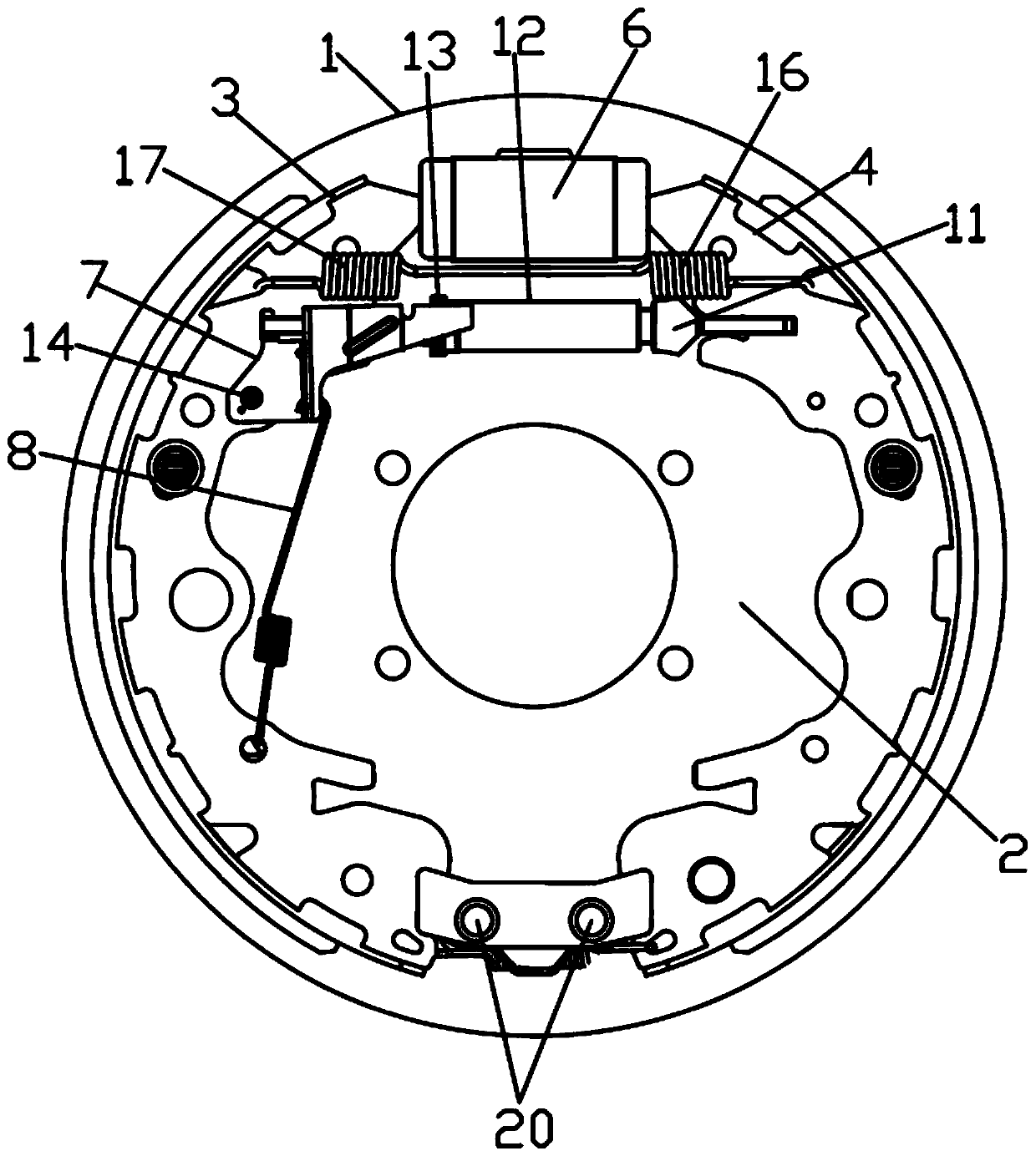
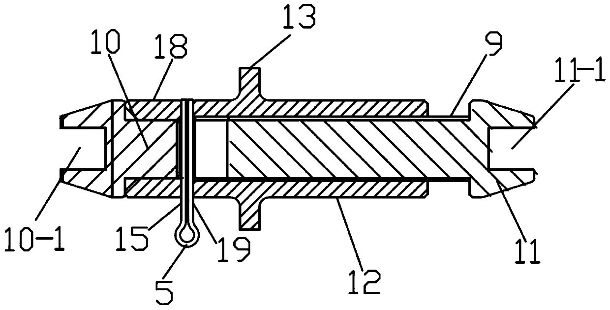
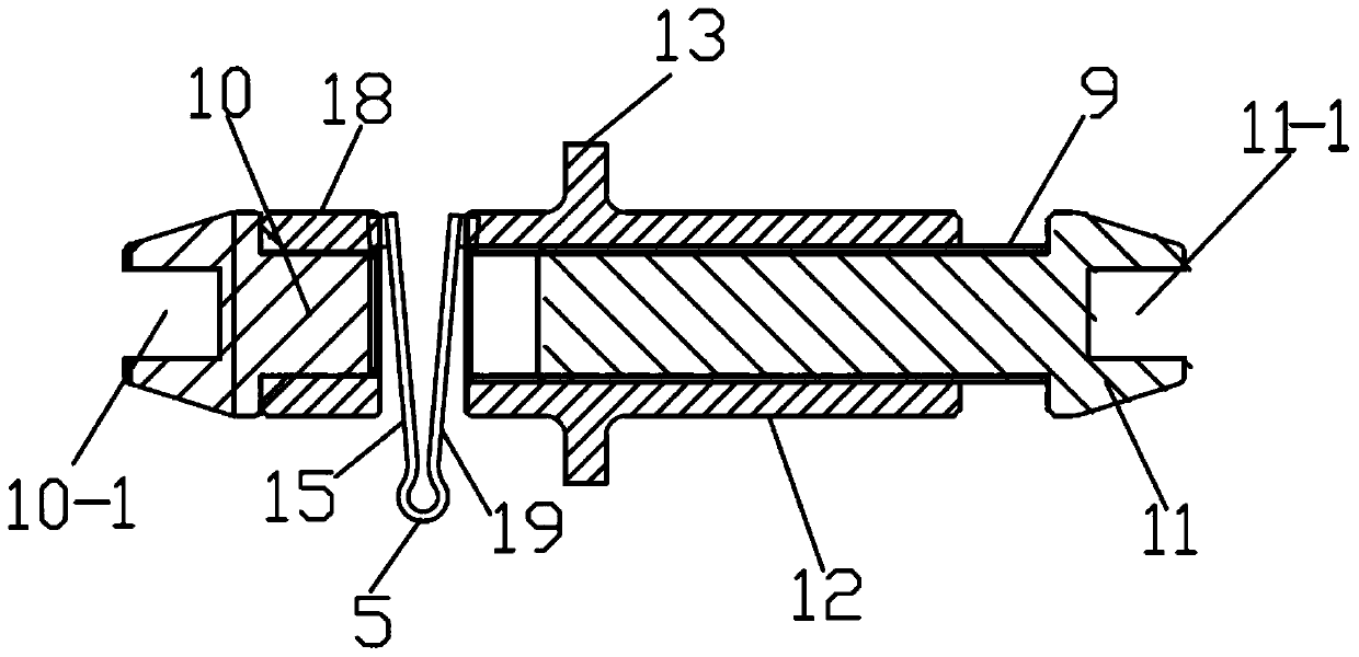
[0020] The present invention will be further described in detail below in conjunction with the accompanying drawings and specific embodiments.

[0021] Depend on Figure 1-4 As can be seen from the illustrated embodiment, this embodiment includes a brake drum 1 with an inner circular friction surface, and the brake leading shoes 3 and the brake slave shoes 4 are symmetrically arranged on the brake bottom plate 2 from left to right, so that the brake leading shoes The arc-shaped friction plates of the brake shoe 3 and the brake slave shoe 4 correspond to the inner circular friction surface of the brake drum 1, and the lower ends of the brake leading shoe 3 and the brake slave shoe 4 are respectively connected to The brake base plate 2 is hinged, and the brake base plate 2 is also provided with a hydraulic cylinder 6 for pushing the upper ends of the brake leading shoe 3 and the brake slave shoe 4 to move to the left and right respectively, and the brake lead shoe 3 and the brak...


PUM


Abstract

The invention discloses a brake, and belongs to the technical field of automobile braking. A compensation gap adjusting ratchet wheel structure, a friction gap self-adjusting stirring plate and a stirring plate return spring are included. The compensation gap adjusting ratchet wheel structure comprises a thermal expansion original piece, a ratchet wheel sleeve, a gap adjusting screw, a braking leading shoe connecting piece, a braking leading shoe connecting piece sleeve, a braking auxiliary shoe connecting piece and a pawl. The ratchet wheel sleeve comprises a sleeve body, a ratchet wheel is arranged in the circumferential direction of the sleeve body, and the thermal expansion original piece is arranged between the braking leading shoe connecting piece sleeve and the ratchet wheel sleeve. The left side of the friction gap self-adjusting stirring plate is rotationally connected with a braking leading shoe through a self-adjusting stirring plate rotation shaft. The middle portion of the friction gap self-adjusting stirring plate is elastically connected with the braking leading shoe or a brake bottom plate through the stirring plate return spring. The right end of the friction gap self-adjusting stirring plate is provided with the pawl matched with the ratchet wheel of the compensation gap adjusting ratchet wheel structure. The brake has the advantages that safety and reliability are achieved, and friction plate abrasion gap and thermal expansion gap adjustment is timely and accurate.

Description

technical field [0001] The invention relates to the technical field of automobile braking. Background technique [0002] At present, there is no overheat protection device applied to automobile brakes, which is prone to high temperature due to friction during the braking process of automobiles, resulting in excessive brake automatic adjustment after thermal expansion, resulting in wheel lockup, brake failure, and wheels cannot move, which cannot ensure safe driving of the vehicle. . [0003] The currently used self-adjusting device for the wear gap of the friction plate is divided into two types: 1. The manual adjustment device relies on manual adjustment. soft dynamics and other issues, endangering driving safety. 2. Automatic reversing adjustment device, due to the driving direction of the car, the forward frequency is far greater than the number of reversing times, so the automatic adjustment device cannot completely compensate for the braking gap caused by the wear of ...

Claims


Application Information

Patent Timeline
IPC IPC(8): F16D51/24F16D65/09F16D65/14F16D65/58F16D121/04
CPCF16D51/24F16D65/09F16D65/14F16D65/58F16D2121/04
Inventor 颜培亮
Owner 霸州市华诚汽车制动器有限公司
Why Eureka
Try Eureka