Eureka AIR delivers breakthrough ideas for toughest innovation challenges, trusted by R&D personnel around the world.

Liquid pipeline dead oil section pressure relief device and method

A technology for liquid pipelines and pressure relief devices, applied in pipeline systems, gas/liquid distribution and storage, mechanical equipment, etc., can solve problems such as personal and property damage, safety accidents, seepage, etc. and property safety, timely alarm speed, high accuracy

Inactive Publication Date: 2019-09-27
BC P INC CHINA NAT PETROLEUM CORP +2
View PDF11 Cites 0 Cited by
  • Summary
  • Abstract
  • Description
  • Claims
  • Application Information

AI Technical Summary

Problems solved by technology

No safety relief valve or thermal expansion valve is installed, resulting in liquid seepage from the flanges of valves and other flanges due to temperature rise in the dead oil section of the liquid pipeline, which eventually leads to safety accidents, causing great adverse effects on society and enterprises , which poses a serious threat to the lives and properties of the people around the pipeline
If the relevant information such as whether the pressure of the pipeline in the dead oil section has risen is not grasped in time, and timely processing is performed, it will cause liquid leakage, causing environmental pollution and personal and property losses.

Method used


Image

  • Liquid pipeline dead oil section pressure relief device and method
  • Liquid pipeline dead oil section pressure relief device and method

Examples


Embodiment 1

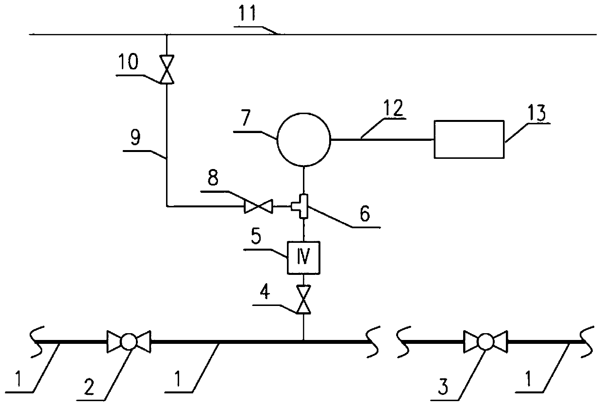
[0031] Such as figure 1 As shown, what is described in the embodiment of the present invention is a pressure relief device for the dead oil section of a liquid pipeline, which includes:

[0032] A liquid pipeline 1 is provided with a first valve 2 and a second valve 3 sequentially from upstream to downstream;

[0033] A pressure monitoring and alarming device 7, which is located on the liquid pipeline 1 between the first valve 2 and the second valve 3, and the pressure monitoring and alarming device 7 is connected to the liquid pipeline 1 through the instrument valve 5;

[0034] Tee 6, which is located between the instrument valve 5 and the pressure monitoring alarm device 7, the instrument valve 5 is connected to the first connection end of the tee 6, and the pressure monitoring alarm device 7 is connected to the second connection end of the tee 6;

[0035] The third valve 8, its inlet end is connected with the third connection end of the tee 6, and the outlet end of the thi...

Embodiment 2

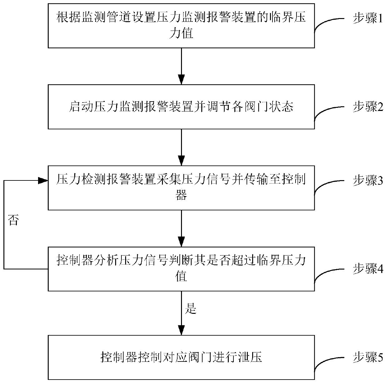
[0045] Such as figure 2 As shown, what is described in the embodiment of the present invention is a method for releasing pressure in a dead oil section of a liquid pipeline, the method comprising:

[0046] Step 1, setting the critical pressure value of the pressure monitoring alarm device 7 and the controller 13 according to the monitored liquid pipeline 1;

[0047] Step 2, start the pressure monitoring and alarm device 7 and make the first valve 2, the second valve 3, the third valve 8 and the fourth valve 10 all in the closed state;

[0048] Step 3, the pressure monitoring and alarming device 7 collects the pressure of the liquid pipeline 1 between the first valve 2 and the second valve 3 in real time, and transmits each collected pressure signal to the controller 13;

[0049] Step 4, the controller 13 analyzes the received pressure signal, and when the pressure signal value exceeds the critical pressure value in step 1, execute step 5, otherwise execute step 3;

[0050] ...


PUM


Abstract

The invention discloses a liquid pipeline dead oil section pressure relief device and method. A liquid pipeline is sequentially provided with a first valve and a second valve from the upstream direction to the downstream direction; a pressure monitoring and warning device is arranged on the liquid pipe between the first valve and the second valve and connected with the liquid pipeline through a gauge valve; a three-way pipe is arranged between the gauge valve and the pressure monitoring and warning device, the gauge valve is connected with the first connecting end of the three-way pipe, and the pressure monitoring and warning device is connected with the second connecting end of the three-way pipe; the inlet end of the third valve is connected with the third connecting end of the three-way pipe, and the outlet end of the third valve is connected with a discharge pipe; and a controller is connected with the pressure monitoring and warning device. The invention further discloses a liquid pipeline dead oil section pressure relief method. The method includes the steps that a critical pressure value is set; the pressure monitoring and warning device is started; the pressure monitoring and warning device acquires the pressure of the liquid pipeline in real time and transmits the pressure to the controller; the controller analyzes the received pressure signals; and if the pressure value exceeds the critical pressure value, the pressure monitoring and warning device gives an alarm, and the controller controls a pressure guide pipe to relieve the pressure.

Description

technical field [0001] The invention relates to the technical field of infusion pipelines, in particular to a pressure relief device and method for a dead oil section of a liquid pipeline. Background technique [0002] During the operation of the liquid pipeline, for the pipeline of the dead oil section, it is not considered in the design process or the temperature rise and expansion of the internal liquid are considered to be within a safe range during the design. No safety relief valve or thermal expansion valve is installed, resulting in liquid seepage from the flanges of valves and other flanges due to temperature rise in the dead oil section of the liquid pipeline, which eventually leads to safety accidents, causing great adverse effects on society and enterprises , It also brings a serious threat to the life and property safety of the people around the pipeline. If the relevant information such as whether the pressure of the pipeline in the dead oil section has risen ...

Claims


Application Information

Patent Timeline
Patent Type & Authority Applications(China)
IPC IPC(8): F17D3/01F17D1/08F17D5/00
CPCF17D1/08F17D3/01F17D5/00
Inventor 聂中文黄晶单超西敬军黄薇薇冯骋于永志刘芳芳
Owner BC P INC CHINA NAT PETROLEUM CORP
Why Eureka
Eureka Blog
Learn More