
Oil-gas pipeline leakage monitoring system based on optical fiber

A technology for oil and gas pipelines and monitoring systems, which is applied in pipeline systems, gas/liquid distribution and storage, mechanical equipment, etc., and can solve problems such as unsatisfactory long-distance monitoring and leakage

Pending Publication Date: 2019-09-27
SHANGHAI JIAO TONG UNIV +1
View PDF0 Cites 8 Cited by
  • Summary
  • Abstract
  • Description
  • Claims
  • Application Information

AI Technical Summary

Problems solved by technology

[0003] The present invention is based on existing The current DAS scheme cannot meet the shortage of long-distance monitoring under the condition of high spatial resolution and high sensitivity. A fiber-based oil and gas pipeline leakage monitoring system is proposed, which combines high-performance distributed fiber-optic acoustic sensing technology and wavelet noise reduction algorithm. Applied to the detection of gas pipeline leaks, the spatial resolution is determined by the scanning range of the detection optical signal and has nothing to do with the duration of the optical pulse, thus solving the traditional The contradiction between spatial resolution and detection distance in the technology can achieve meter-level high spatial resolution, high sensitivity and long sensing distance, and at the same time remove the influence of environmental noise, significantly improving the detection sensitivity of weak leakage signals

Method used


Image

  • Oil-gas pipeline leakage monitoring system based on optical fiber
  • Oil-gas pipeline leakage monitoring system based on optical fiber
  • Oil-gas pipeline leakage monitoring system based on optical fiber

Examples


Embodiment Construction

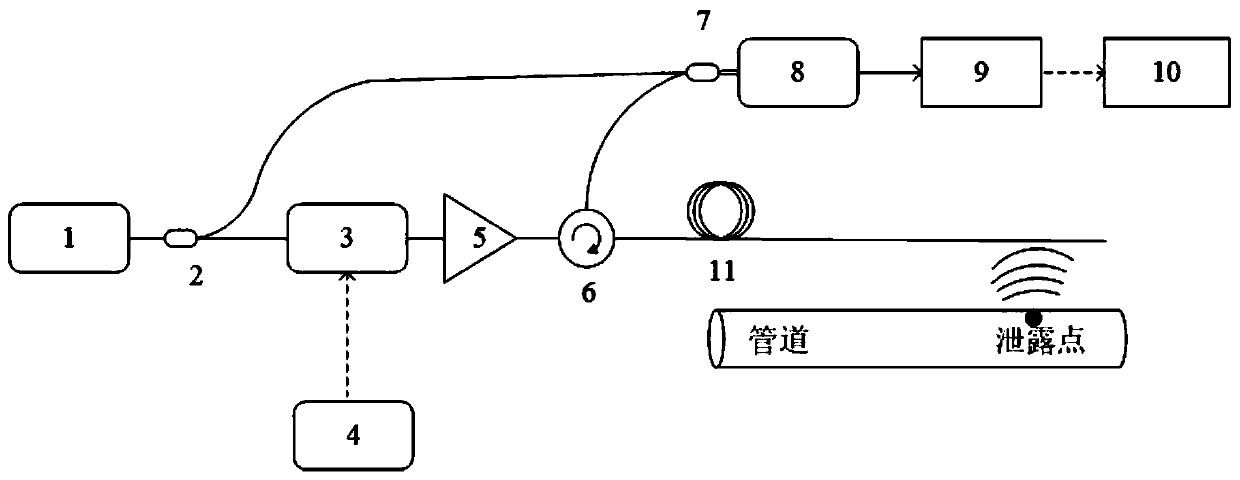
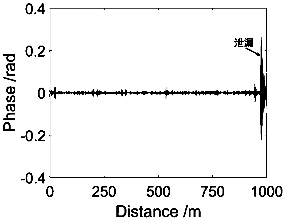
[0020] This example figure 1 and figure 2 As shown, the pipeline leakage simulation experiment is as follows: a small hole with a diameter of 4.2mm is drilled on a metal pipeline with a length of 12m and a diameter of 32mm as a leakage hole. One end of the pipeline is sealed, and the other end is connected to the pressure tank through a transmission pipe. superior. Fill the pipe with soil until it is covered to simulate a buried pipe. After filling a certain thickness of soil, lay a 50m armored optical fiber to be tested on the soil, such as figure 2 As shown, continue to fill the cable with soil to completely cover the cable. The armored optical cable is connected to the DAS demodulator after passing through about 950m of transmission optical cable. For each experiment, the pressure parameters on the pressure tank are changed first, and gases of different pressures are sent to the pipeline to simulate the strength of the pipeline leakage.

[0021] Such as figure 1 As ...


PUM


Abstract

The invention discloses an oil-gas pipeline leakage monitoring system based on an optical fiber. The system involves a DAS system based on a time-gated optical frequency domain reflectometer, a signal processor and an optical fiber to be tested, wherein the optical fiber to be tested is arranged at an input end of the DAS system, and the signal processor is arranged at an output end of the DAS system. According to the system, a high-performance distributed optical fiber acoustic wave sensing technology and a wavelet noise reduction algorithm are applied to detection of gas pipeline leakage, the spatial resolution is determined by the frequency sweeping range of a detection optical signal and is independent of the duration of a optical pulse, so that the contradiction between the spatial resolution and the detection distance in the prior art is solved, the meter-scale high-spatial resolution, high sensitivity and long sensing distance can be realized, and meanwhile, the influence of ambient noise is eliminated, so that the detection sensitivity to weak leakage signals is remarkably improved.

Description

technical field [0001] The invention relates to a technology in the application field of optical fiber sensors, in particular to an oil and gas pipeline leakage monitoring system based on distributed optical fiber sensing technology, which realizes real-time monitoring and positioning of oil and gas pipeline leakage. Background technique [0002] Nowadays, the real-time and accurate detection of pipeline leakage is realized by optical fiber distributed acoustic sensor (DAS), among which the more commonly used one is based on phase-sensitive optical time domain reflectometer Pipeline monitoring technology has the following disadvantages: There is a contradictory relationship between the spatial resolution of the sensor and the sensing distance: the shorter the duration of the detection light pulse, the higher the spatial resolution, but this will lead to a decrease in pulse energy, a decrease in the signal-to-noise ratio of Rayleigh scattered light, and a 2) The coherent f...

Claims


Application Information

Patent Timeline
IPC IPC(8): F17D5/06
CPCF17D5/06
Inventor 刘庆文何祖源王辰陈典
Owner SHANGHAI JIAO TONG UNIV
Learn More