
Liquid viscosity coefficient measuring device and working method

A technology of viscosity coefficient and measuring device, applied in the field of experimental tools, can solve the problems of measurement errors, unguaranteed accuracy, and difficulty in uniform movement of small balls, and achieve the effects of reducing timing errors, expanding research scope, and improving scientificity.

Pending Publication Date: 2019-09-27
SHANDONG FIRST MEDICAL UNIV & SHANDONG ACADEMY OF MEDICAL SCI
View PDF0 Cites 3 Cited by
  • Summary
  • Abstract
  • Description
  • Claims
  • Application Information

AI Technical Summary

Problems solved by technology

The inventor found that the traditional falling ball method has obvious shortcomings, and encountered problems in the precise measurement of general liquids: if a stopwatch is used for manual timing, there will be errors in the measurement, so that the accuracy cannot be guaranteed, and it is difficult to judge whether the ball has moved at a uniform speed. The reliability of the measured value is reduced. When a large amount of experimental data is required, fast and accurate measurement cannot be achieved, it is difficult to ensure that the ball falls vertically along the center line, and the viscosity coefficient of opaque liquid cannot be measured, etc.
However, the inventor found that the current experimental scheme adopted abroad not only cannot scientifically control the throwing point and trajectory of the ball, but also cannot reduce the additional impact brought by the difference in the initial velocity of the ball, and the accuracy of the experimental data still needs to be improved

Method used


Image

  • Liquid viscosity coefficient measuring device and working method
  • Liquid viscosity coefficient measuring device and working method
  • Liquid viscosity coefficient measuring device and working method

Examples


Embodiment Construction

[0033] It should be pointed out that the following detailed description is exemplary and intended to provide further explanation to the present application. Unless defined otherwise, all technical and scientific terms used herein have the same meaning as commonly understood by one of ordinary skill in the art to which this application belongs.

[0034]It should be noted that the terminology used here is only for describing specific implementations, and is not intended to limit the exemplary implementations according to the present application. As used herein, unless the context clearly dictates otherwise, the singular is intended to include the plural, and it should also be understood that when the terms "comprising" and / or "comprising" are used in this specification, they mean There are features, steps, operations, means, components and / or combinations thereof.

[0035] For the convenience of description, if the words "up", "down", "left" and "right" appear in the present in...


PUM

PropertyMeasurementUnit
diameteraaaaaaaaaa

Abstract

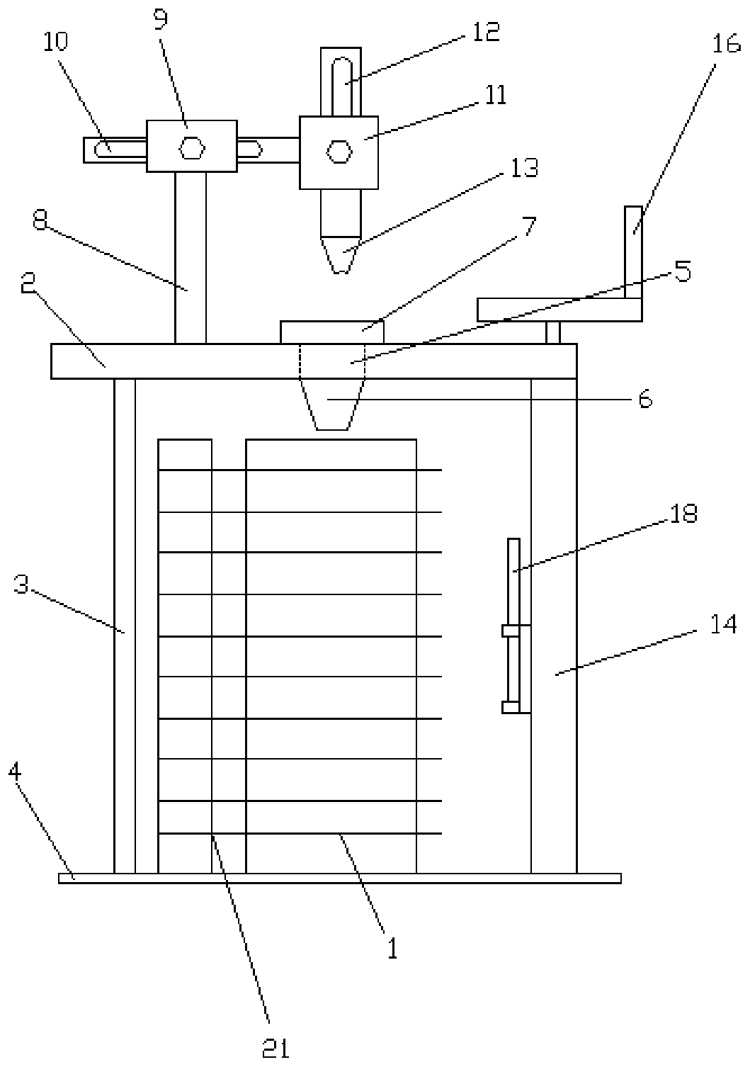
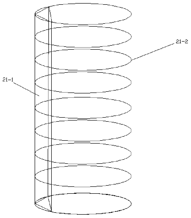
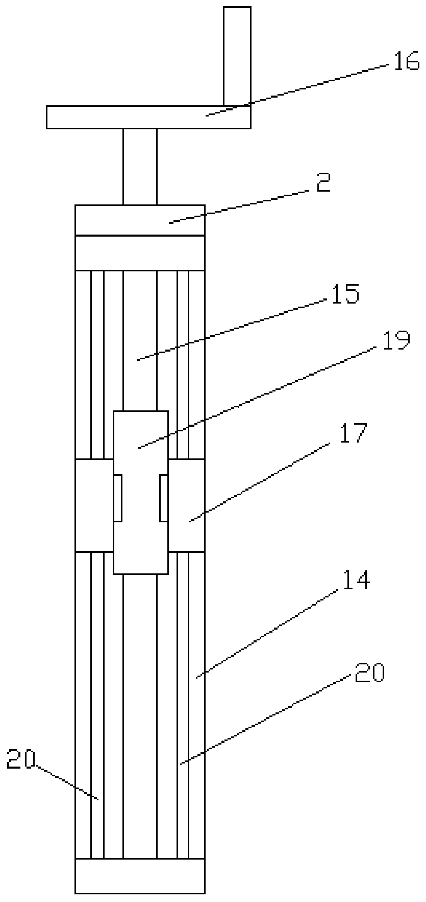
The invention relates to a liquid viscosity coefficient measuring device and a working method. The liquid viscosity coefficient measuring device comprises a liquid accommodating device, wherein a cross beam is arranged above the liquid accommodating device; an aligning mechanism is fixedly arranged on the cross beam; the aligning mechanism is positioned over the liquid accommodating device, and is used for adjusting a small ball used for experiments to fall off along the vertical direction; a support is arranged on one side of the aligning mechanism; the support is connected with an electromagnet through an adjusting mechanism; the adjusting mechanism can adjust the positions of the electromagnet in the vertical direction and the vertical direction; the electromagnet is used for adsorbing the small ball used for experiments; a picture recording device support is arranged on one side of the liquid accommodating device; a lifting mechanism is arranged on the picture recording device support; the lifting mechanism is connected with a picture recording device; the picture recording device is used for recording pictures in the falling process of the small ball. The measuring device is convenient to use, high in measuring efficiency and accurate in measuring results.

Description

technical field [0001] The invention relates to the technical field of experimental tools, in particular to a liquid viscosity coefficient measuring device and a measuring method. Background technique [0002] The viscosity coefficient of liquid reflects the resistance of an object when it passes through the fluid. If the viscosity coefficient is large, the resistance to the moving object is large. Viscosity coefficient is one of the most important parameters to describe the properties of fluid, and it is an important parameter in fluid mechanics. In industrial production and scientific research, the measurement of viscosity coefficient has great practical significance. In many engineering applications, fluid is used as the engine of hydraulic system and hydraulic power lubrication, the selection of lubricating oil used in various machinery, hydraulic transmission, and the study of actual fluid motion laws all require the determination of the viscosity coefficient of the flu...

Claims


Application Information

Patent Timeline
Patent Type & Authority Applications(China)
IPC IPC(8): G01N11/12
CPCG01N11/12
Inventor 董克江刘相恩侯坤王淑婷史胜宁谢同琪
Owner SHANDONG FIRST MEDICAL UNIV & SHANDONG ACADEMY OF MEDICAL SCI
Learn More