
Antenna device and electronic equipment

A technology of antenna device and electronic equipment, applied in the direction of antenna support/mounting device, antenna, antenna coupling, etc., which can solve the problems of being easily affected by noise interference, easily affected by thermal shock, and poor antenna network stability

Active Publication Date: 2019-09-27
SHANGHAI CHUANGGONG COMM TECH
View PDF9 Cites 1 Cited by
  • Summary
  • Abstract
  • Description
  • Claims
  • Application Information

AI Technical Summary

Problems solved by technology

However, the inventors have found that there are at least the following problems in the prior art: the network traces from the existing capacitive sensor to the antenna are very long and are very susceptible to noise interference; and when the traces pass through heat source areas (such as CPU / DDR / PA) , very susceptible to thermal shock, resulting in poor stability of the antenna network

Method used


Image

  • Antenna device and electronic equipment
  • Antenna device and electronic equipment
  • Antenna device and electronic equipment

Examples


Embodiment Construction

[0017] In order to make the purpose, technical solutions and advantages of the embodiments of the present invention more clear, various implementation modes of the present invention will be described in detail below in conjunction with the accompanying drawings. However, those of ordinary skill in the art can understand that, in each implementation manner of the present invention, many technical details are provided for readers to better understand the present application. However, even without these technical details and various changes and modifications based on the following embodiments, the technical solution claimed in this application can also be realized; and the division of the following embodiments is for convenience of description, and should not be used for the specific implementation of the present invention The mode constitutes any limitation, and the various implementation modes can be combined with each other and utilized on the premise of no contradiction.

[0...


PUM


Abstract

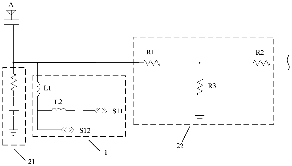
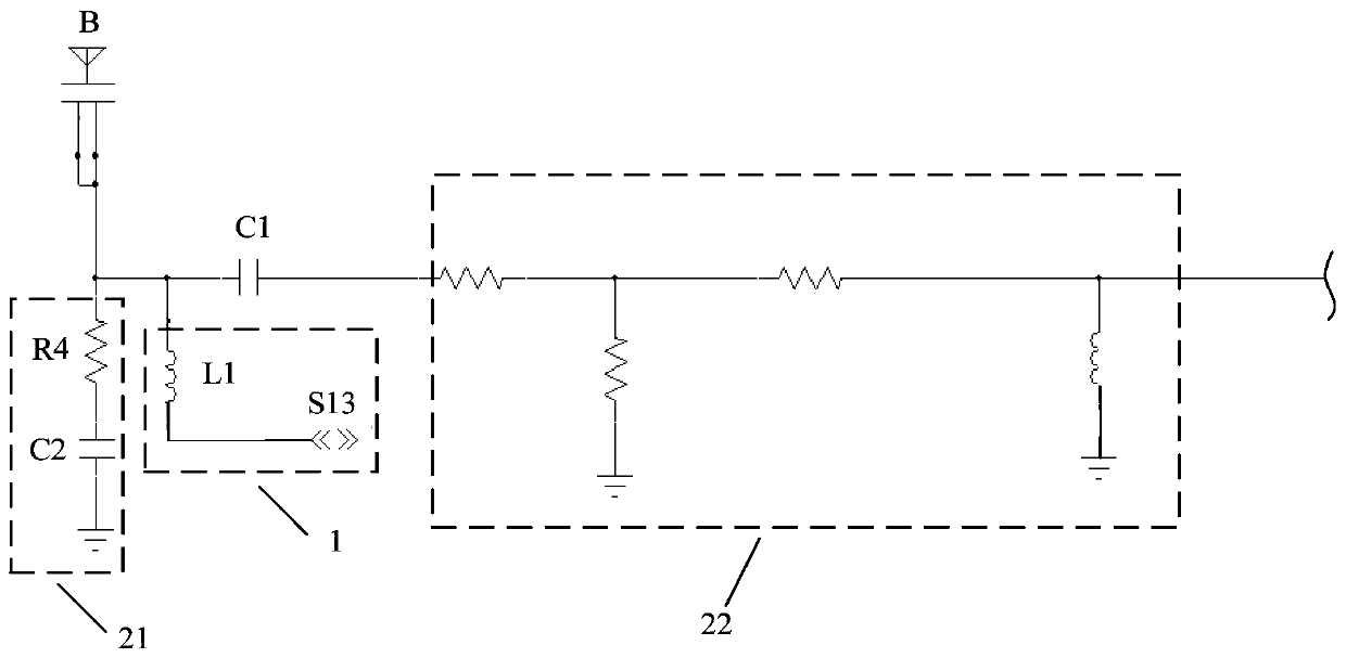
Some embodiments of the invention relate to the technical field of electronic products, and disclose an antenna device and electronic equipment. In the embodiment of the invention, the antenna device is applied to the electronic equipment comprising a circuit board. The antenna device comprises an SAR reduction branch and an antenna which are arranged on the circuit board. The SAR reduction branch at least comprises a capacitive sensor, and is connected to the antenna, wherein a preset distance is set between the capacitive sensor and the antenna; an induction channel of the capacitive sensor and an adjacent reference channel are connected to the antenna in a routing manner. Some embodiments of the invention also provide the electronic equipment. According to the embodiment of the invention, a common-mode noise signal is suppressed, and the circuit stability is greatly improved.

Description

technical field [0001] Some embodiments of the present invention relate to the technical field of electronic products, in particular to an antenna device and electronic equipment. Background technique [0002] Mobile phones, computers and other electronic devices are widely used in people's daily life, and the terminal is usually relatively close to the human body. In order to keep the influence of the electromagnetic waves radiated by the antenna in the terminal on the human body within a safe range, CE certification and FCC certification have strict requirements on SAR ( Electromagnetic wave specific absorption rate) requirements are also more stringent, therefore, the antenna in the terminal must meet the SAR index requirements. [0003] At present, the use of capacitive sensors to achieve SAR reduction is the mainstream SAR reduction solution. In the existing SAR reduction circuit, the capacitive sensor is connected to any antenna that needs to reduce SAR through single-...

Claims


Application Information

Patent Timeline
Patent Type & Authority Applications(China)
IPC IPC(8): H01Q1/52H01Q1/22H01Q23/00
CPCH01Q1/22H01Q1/52H01Q23/00
Inventor 赵鑫
Owner SHANGHAI CHUANGGONG COMM TECH
Learn More