
Device for heating ends of stabilizer bar

A technology for heating equipment and stabilizer bars, applied in metal processing equipment, metal processing, forming tools, etc., can solve the problems of uneven heating, low mechanical properties of the end, and increased driving safety hazards, and achieve precise control of heating temperature and heat treatment. Good effect, avoid fatigue failure effect

Inactive Publication Date: 2019-10-01
盐城恒胜数控科技有限公司
View PDF6 Cites 1 Cited by
  • Summary
  • Abstract
  • Description
  • Claims
  • Application Information

AI Technical Summary

Problems solved by technology

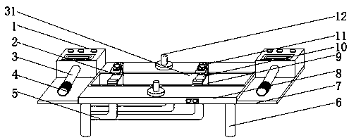
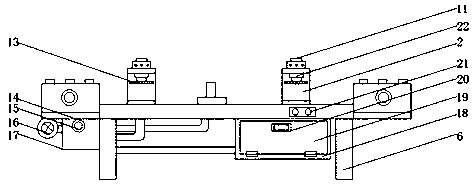
[0004] The purpose of the present invention is to provide a kind of stabilizer rod end heating equipment, to solve the current production proposed in the above background technology, in order to facilitate the connection between the automobile stabilizer rod and the automobile suspension, the end of the stabilizer rod needs to be forged into a certain shape, This will cause a large difference in the shape of the end section of the stabilizer bar and the section of the stabilizer bar body. When using the traditional resistance heating method to clamp the end part, due to the different cross-sectional shapes, the resulting resistance is different, resulting in uneven heating. The end part is easy to be fused. In order to prevent the end of the stabilizer bar from being fused during the production of the variable cross-section stabilizer bar, the heating electrode only clamps and heats the middle part of the stabilizer bar, but cannot heat the ends of the stabilizer bar. After the heat treatment of the stabilizer bar , the hardness of the two ends is low, the metallographic structure has not changed, the performance of the end of the stabilizer bar and the heated part of the stabilizer bar are inconsistent, the mechanical properties of the end are low, and the end of the stabilizer bar is prone to fatigue failure during driving. , the problem of increased driving safety hazards

Method used


Image

  • Device for heating ends of stabilizer bar
  • Device for heating ends of stabilizer bar
  • Device for heating ends of stabilizer bar

Examples


Embodiment Construction

[0022] The following will clearly and completely describe the technical solutions in the embodiments of the present invention with reference to the accompanying drawings in the embodiments of the present invention. Obviously, the described embodiments are only some, not all, embodiments of the present invention. Based on the embodiments of the present invention, all other embodiments obtained by persons of ordinary skill in the art without making creative efforts belong to the protection scope of the present invention.

[0023] In the description of the present invention, it should be noted that the terms "upper", "lower", "inner", "outer", "front end", "rear end", "both ends", "one end", "another end" The orientation or positional relationship indicated by etc. is based on the orientation or positional relationship shown in the drawings, which is only for the convenience of describing the present invention and simplifying the description, rather than indicating or implying tha...


PUM


Abstract

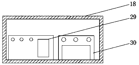
The invention discloses a device for heating ends of a stabilizer bar. The device comprises a heating machine, a heating coil, a frame and a controller, wherein a sliding groove is formed in the top surface of the frame; sliding blocks are movably arranged on the two sides in the sliding groove; sleeves are fixedly arranged on the two sides of each sliding block; springs are arranged on the innersides of the sleeves through fixing blocks; positioning heads are fixedly arranged at the outer ends of the springs; and positioning grooves are formed in the inner walls of the two sides of the sliding groove. According to the device, the structure is reasonable; and through a series of structures, the middle part of the stabilizer bar is heated firstly by adopting an electrode, then, after the set temperature is reached, the ends of the stabilizer bar are heated by using the heating machine, therefore, the middle part and the ends of the stabilizer bar can keep the same heating temperature,the ends and the middle part of the stabilizer bar are consistent in metallographic structure transformation and the same in hardness during heat treatment, and the failure of the stabilizer bar due to fatigue can be avoided.

Description

technical field [0001] The invention belongs to the technical field of mechanical processing equipment, and in particular relates to a heating equipment for the end of a stabilizer bar. Background technique [0002] The full name of the stabilizer bar is "horizontal stabilizer bar", also known as torsion bar spring, which is an auxiliary elastic component in the car suspension. Its function is to prevent the body from excessive lateral roll when turning. The purpose is to prevent the car from tilting laterally and improve ride comfort. The stabilizer bar is a torsion bar spring made of spring steel. It is in the shape of a "U" and is placed horizontally on the front and rear ends of the car. The middle part of the bar is hinged to the frame with a sleeve, and the two ends of the bar are respectively fixed. On the left and right hanging lower brackets or shock absorber struts, at present, in the production industry of automobile stabilizer bars, a commonly used process is to...

Claims


Application Information

Patent Timeline
Patent Type & Authority Applications(China)
IPC IPC(8): B21D7/16B21D37/16B21C51/00B21J1/06
CPCB21C51/00B21D7/162B21J1/06
Inventor 陈新
Owner 盐城恒胜数控科技有限公司
Learn More