

Self-lubricating structure of double-row heavy-load cement conveying chain
Patent Information
- Authority / Receiving Office
- CN · China
- Current Assignee / Owner
- 安徽黄山中友链条制造有限公司
- Publication Date
- 2019-10-01
- Estimated Expiration
- Not applicable · inactive patent
Smart Images
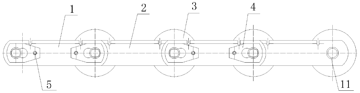
Figure 1 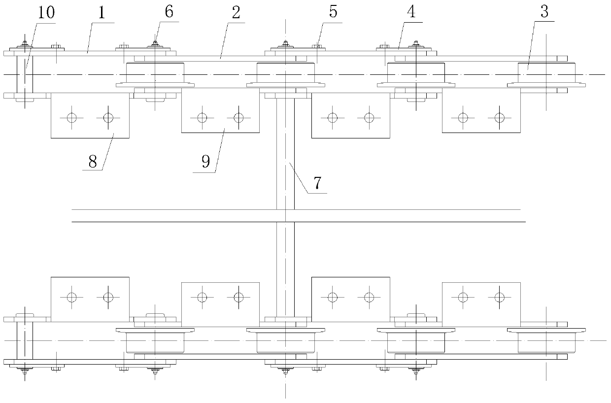
Figure 2 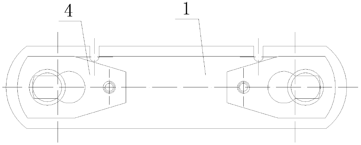
Figure 3
Abstract
Description
technical field
[0001] The invention relates to the technical field of self-lubricating conveyor chains, in particular to a self-lubricating structure of a double-row heavy-duty cement conveyor chain. Background technique
[0002] The heavy-duty cement conveyor chain is mainly used for various conveying equipment in cement plants. It is mainly used in limestone reclaimers, coal and concrete conveyors, bucket elevators, clinker conveyors and other equipment. The chain is the transmission of these conveying equipment Parts, transmitting motion and power, conveying limestone, coal slag, stone clinker and other materials, the working conditions are very harsh, the load is relatively large, and the wear is relatively severe, which requires the chain to be resistant to high temperature, wear and fatigue. .
[0003] The two chains are connected in series by lengthening the pin shaft to form a set of double-row chains. When the chains are running on the machine, they must run synch...