Fixed-frequency variable flow condensation unit system

A condensing unit and variable flow technology, which is applied in the direction of refrigerators, refrigeration components, compressors, etc., can solve the problems of difficult return of lubricating oil to the compressor, slow flow rate of refrigerant, interference, etc., to avoid the problem of high point interference and additional noise , avoid lubricating oil problems, and solve the effect of frequency conversion interference problems

Inactive Publication Date: 2019-10-01
南京师范大学镇江创新发展研究院
View PDF6 Cites 9 Cited by
  • Summary
  • Abstract
  • Description
  • Claims
  • Application Information

AI Technical Summary

Problems solved by technology

[0003] The disadvantages of the above-mentioned prior art are: the multi-connected air-conditioning system with variable frequency and variable flow has very high requirements on pipe material and manufacturing process, and its initial investment is relatively high; AC frequency conversion will generate high-order harmonics, which is harmful to precision instruments and electronic computers. The equipment is disturbed and will generate extra noise; in addition, when the frequency of the motor is low, due to the slow flow rate of the refrigerant, it will be difficult for the lubricating oil to flow back to the compressor. When the frequency of the motor is high, a large amount of lubricating oil will be squeezed out of the compressor. lubricating oil problem

Method used


Image

  • Fixed-frequency variable flow condensation unit system
  • Fixed-frequency variable flow condensation unit system
  • Fixed-frequency variable flow condensation unit system

Examples


Embodiment 1

[0020] Example 1 Full load operation

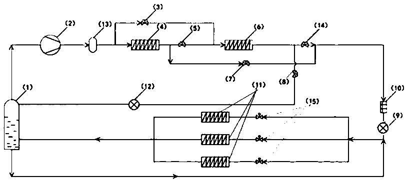
[0021] refer to figure 2 , when the system is running at full load, the first flow regulating valve 3 is closed, the first solenoid valve 5 and the fourth solenoid valve 14 are opened, the second solenoid valve 7 and the third solenoid valve 8 are closed, the bypass refrigerant passage is closed, all The refrigerant all enters the evaporator group 11 for refrigeration. The refrigerant passage is as follows: the refrigerant gas enters the condenser 4 to condense, and then enters the subcooler 6 for recooling, and the recooled refrigerant enters the drying filter 10 and the first throttle valve 9, and then flows through the flow regulating valve 15 to divert into evaporation The evaporator group 11 evaporates and refrigerates, and then enters the gas-liquid separator 1. The separated gas enters the compressor 2 and the oil separator 13 and returns to the condenser 4. The separated liquid enters the suction port of the evaporator group 11,...

Embodiment 2

[0022] Example 2 Bypass refrigerant cooling to saturated gas state

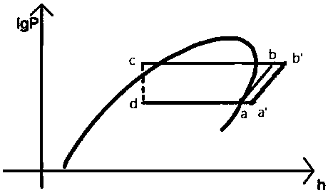
[0023] refer to image 3 , when the partial load of the system is adjusted, the first solenoid valve 5 and the fourth solenoid valve 14 are closed, the second solenoid valve 7 and the third solenoid valve 8 are opened, and the first flow regulating valve 3 is opened. The refrigerant is discharged from the compressor 2 and passes through the oil separator 3, and the refrigerant is divided into two paths. One of the refrigerants enters the condenser 4 to condense, passes through the second solenoid valve 7, the dry filter 10, and the first throttle valve 9 to throttle, and after the second flow regulating valve 15, it diverts into the evaporator group 11 for cooling, and enters the gas-liquid Separator 1. Another path of refrigerant passes through the first flow regulating valve 3 , the subcooler 6 , the third solenoid valve 8 , and the second throttle valve 12 , and enters the gas-liquid separator 1 . After...

Embodiment 3

[0024] Example 3 Bypass refrigerant cooling to two-phase region

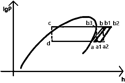
[0025] refer to Figure 4 , when the partial load of the system is adjusted, the first solenoid valve 5 and the fourth solenoid valve 14 are closed, the second solenoid valve 7 and the third solenoid valve 8 are opened, and the first flow regulating valve 3 is opened. The refrigerant is discharged from the compressor 2 and passes through the oil separator 3, and the refrigerant is divided into two paths. One of the refrigerants enters the condenser 4 to condense, passes through the second electromagnetic valve 7, the drier filter 10, the first throttle valve 9 to throttle, and after the second flow regulating valve 15, it is diverted into the evaporator group 11 for cooling, and enters the gas Liquid separator 1. Another path of refrigerant passes through the first flow regulating valve 3 , the subcooler 6 , the third solenoid valve 8 , and the second throttle valve 12 , and enters the gas-liquid separator 1 ....


PUM


Abstract

The invention relates to a fixed-frequency variable flow condensation unit system. The fixed-frequency variable flow condensation unit system comprises a condenser, a re-cooling device, four electromagnetic valves, a flow adjusting valve, a plurality of evaporators, a compressor, two throttling valves, a dry filter, an oil separator and a gas-liquid separator. The requirement for variable load running of the different evaporators can be met only through control over the opening and closing of a condensation unit valve and the aperture of the flow adjusting valve. According to a condensation unit, the refrigerant flow can be effectively controlled, and usage of the multiple evaporators and system loads are effectively matched. One feature is that by control over opening and closing of the electromagnetic valves and the aperture of the flow adjusting valve, the flow of the refrigerant entering the evaporators can be controlled, the bypass refrigerant is treated to the proper state, and accordingly the bypass refrigerant and the refrigerant at evaporator outlets can be mixed in the gas-liquid separator to be continuously and cyclically used. The fixed-frequency variable flow condensation unit system has the advantages that frequency conversion treatment is not needed, the system structure is simple, and the problems about frequency conversion interference and noise are solved.

Description

technical field [0001] The invention relates to a condensing unit and an air-conditioning system in the technical field of air-conditioning equipment, in particular to a fixed-frequency variable-flow condensing unit system. Background technique [0002] The existing variable flow condensing unit system generally adopts variable frequency variable flow multi-connected air conditioning system, that is, through frequency conversion to adjust the air delivery volume of the compressor and the refrigerant flow rate entering the indoor unit, so as to meet the cooling and heating output requirements of different spaces. Frequency conversion regulation is divided into DC frequency conversion and AC frequency conversion. DC frequency conversion is actually DC speed regulation. By changing the DC voltage sent to the motor to change the speed of the motor, thereby changing the flow of refrigerant. AC frequency conversion changes the speed of the motor by changing the frequency and volta...

Claims


Application Information

Patent Timeline
Patent Type & Authority Applications(China)
IPC IPC(8): F25B5/02F25B41/00F25B41/40
CPCF25B5/02F25B41/00
Inventor 牛宝联张忠斌王必成顾希娴
Owner 南京师范大学镇江创新发展研究院
Why Eureka
Try Eureka