
A metal pipe finishing processing equipment

A technology for metal pipes and processing equipment, applied in metal processing equipment, metal processing mechanical parts, shearing machine equipment, etc. Conducive to stable compression and the effect of ensuring safe use

Active Publication Date: 2020-12-22
临沂市皓正铁塔制造有限公司
View PDF1 Cites 0 Cited by
  • Summary
  • Abstract
  • Description
  • Claims
  • Application Information

AI Technical Summary

Problems solved by technology

However, the current cutting processing equipment for metal pipes has the following disadvantages: 1. It does not have the function of compaction, or the compaction effect is poor, which is not conducive to the stable compaction of metal pipes, and it is easy to cause displacement of metal pipes during cutting. Affect the processing accuracy; 2. When cutting thin-walled metal pipes, the metal pipe cannot be firmly supported from the inside. During the cutting process, the thin-walled metal pipe may be forced to deform at the cutting point, which will affect the safe use of the metal pipe.
[0004] In response to the above shortcomings, relevant units in the industry have also conducted research and proposed specific technical solutions. For example, the patent number CN201510642343.2 proposed a solution, but the above problems have not been well resolved

Method used


Image

  • A metal pipe finishing processing equipment
  • A metal pipe finishing processing equipment
  • A metal pipe finishing processing equipment

Examples


Embodiment Construction

[0029] Embodiments of the present invention will be described below with reference to the drawings. In the process, in order to ensure the clarity and convenience of illustration, we may exaggerate the width of the lines or the size of the constituent elements in the diagram.

[0030] In addition, the following terms are defined based on the functions in the present invention, and may be different according to the user's or operator's intention or practice. Therefore, these terms are defined based on the entire content of this specification.

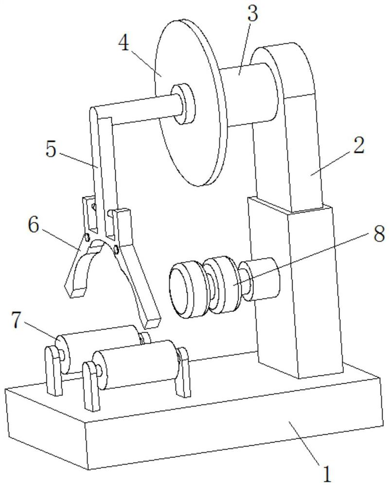
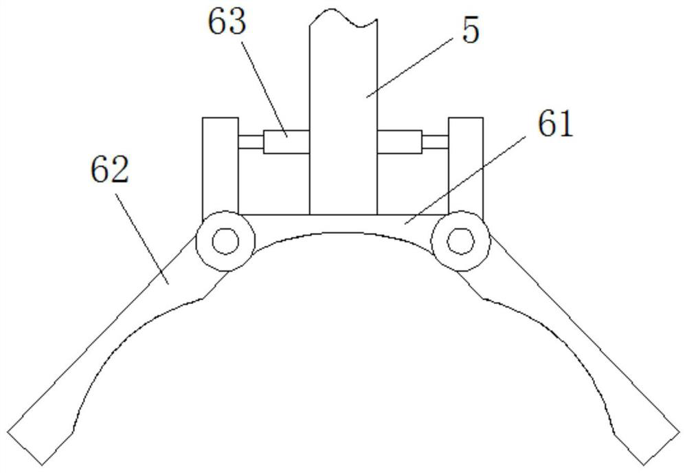
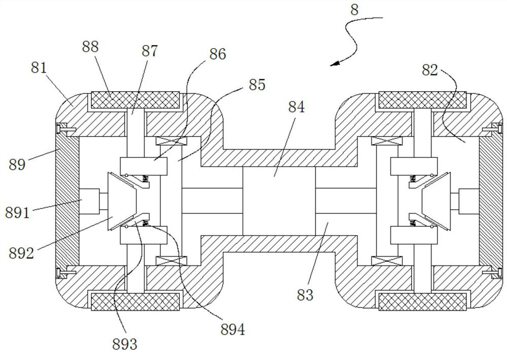
[0031] Such as figure 1 As shown, a metal pipe finish processing equipment includes a base 1 arranged horizontally, a motor telescopic arm 2 is vertically provided at the right end of the base 1, a motor 3 is horizontally provided at the top of the motor telescopic arm 2, and a motor 3 is provided on the output shaft of the motor 3. There is a cutting piece 4, and the inner side of the motor telescopic arm 2 is provided with a stabiliz...


PUM


Abstract

The invention relates to metal pipe finish machining equipment comprising a base arranged horizontally. The right end of the base is vertically provided with a motor telescopic arm of which the top end is provided with a motor horizontally, and an output shaft of the motor is provided with a cutting disk; the inner side of the motor telescopic arm is provided with a securing mechanism through a horizontal cylinder, and the left end of the base is provided with support rollers; and a cross shaft is arranged at the center position of the left side of the cutting disk through a bearing, and the left end of the cross shaft is provided with a main pressing cylinder of which the bottom end is provided with a pressing mechanism. The metal pipe finish machining equipment has the pressing functionand good pressing effect, and benefits stable pressing of a metal pipe; displacement of the metal pipe is avoided in the cutting process, and the machining precision is ensured; during cutting of a thin-walled metal pipe, the metal pipe can be firmly supported internally, and deformation of the cutoff position of the thin-walled metal pipe is avoided in the cutting process; and the safe use of themetal pipe is ensured.

Description

technical field [0001] The invention relates to the technical field of metal pipe finish processing, in particular to a metal pipe finish processing equipment. Background technique [0002] Metal pipe is a common industrial product, mainly used for the transportation of high-pressure fluid. It specifically includes steel pipes, cast iron pipes, non-ferrous metal pipes, metal wires, etc. Among them, steel pipes are divided into two types: seamless steel pipes and welded steel pipes. Metal pipes have the advantages of good heat resistance, non-combustibility, small property changes with temperature changes, high mechanical strength, and not easy to age. Therefore, metal pipes can adapt to harsh working environments. [0003] In the actual use of metal pipes, metal pipes of different lengths are often required according to the usage scenarios, which requires the use of cutting processing equipment to cut the metal pipes. However, the current cutting processing equipment for m...

Claims


Application Information

Patent Timeline
Patent Type & Authority Patents(China)
IPC IPC(8): B23Q3/06B23D21/00
CPCB23D21/00B23Q3/06
Inventor 郭颂姚维杰张金峰
Owner 临沂市皓正铁塔制造有限公司
Learn More