Lateral secondary core-pulling injection mould applied to coffee machine handle production

A secondary core-pulling and injection-mold technology, which is applied in the field of side core-pulling mechanisms, can solve the problem that the injection mold cannot be attached to the injection machine, etc., and achieve the effects of simple and low installation, low manufacturing cost, and low maintenance cost.

Pending Publication Date: 2019-10-08
GUANGDONG SONGSHAN POLYTECHNIC COLLEGE
View PDF0 Cites 3 Cited by
  • Summary
  • Abstract
  • Description
  • Claims
  • Application Information

AI Technical Summary

Problems solved by technology

[0004] The above-mentioned technical solution has defects: due to the structure of the plastic product, it is necessary to put a small row in the large row of side core-pulling, and because the stroke of the large row is very long, the traditional method is to use a large row of side core-pulling structure. After the position is connected with an oil cylinder, when the movable mold and the fixed mold are opened to each other, the inclined guide column fixed on the fixed mold is used to drive the small slider back to the position by using the mold opening force, and then the oil cylinder drives the large row to move backward. , so that the oil cylinders on both sides will far exceed the distance between the green columns of the injection machine, so that the injection mold with the existing side core-pulling mechanism cannot be installed on the injection machine, so it needs to be improved

Method used


Image

  • Lateral secondary core-pulling injection mould applied to coffee machine handle production
  • Lateral secondary core-pulling injection mould applied to coffee machine handle production
  • Lateral secondary core-pulling injection mould applied to coffee machine handle production

Examples


Embodiment Construction

[0023] The present invention will be described in detail below with reference to the drawings and embodiments.

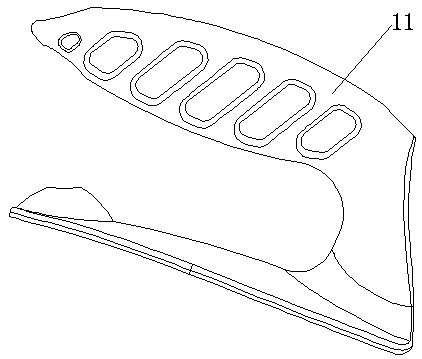
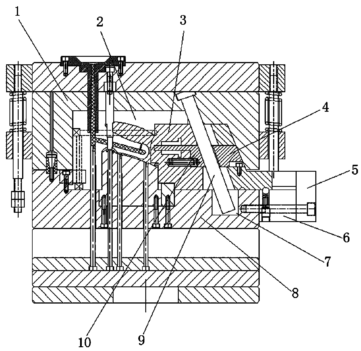
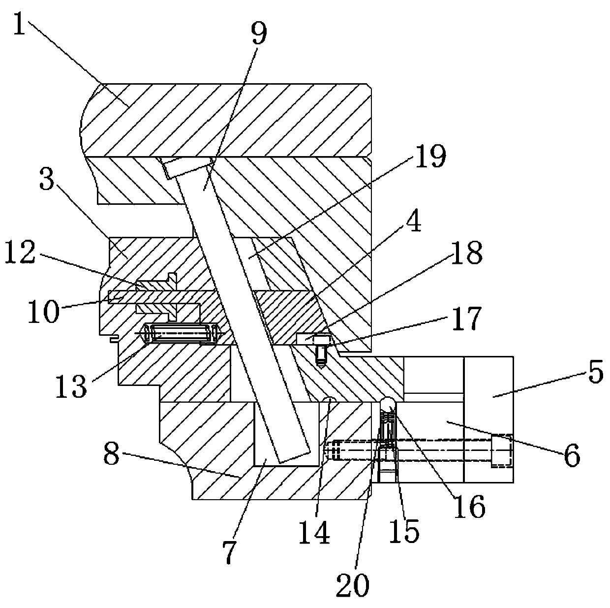
[0024] Such as figure 1 As shown, a lateral secondary core-pulling injection mold used in the production of coffee machine handles. The injection mold includes a movable mold 8 and a fixed mold 1. A molding cavity 2 is formed between the fixed mold 1 and the movable mold 8. The opening and closing directions of the mold are arranged along the up and down direction of the movable mold 8. The movable mold 8 is equipped with a lateral secondary core pulling mechanism. The secondary core pulling mechanism includes a side sliding block 3, a sliding block 10, a rear sliding block 4 and The inclined guide post 9, the side sliding block 3 is slidably mounted on the movable mold 8 along the left and right direction of the movable mold 8, and the side sliding block 3 extends into the molding cavity 2, and the top end of the inclined guide post 9 is installed on the fixed mold 1. ...


PUM


Abstract

The invention relates to the technical field of lateral core-pulling mechanisms, in particular to a lateral secondary core-pulling injection mould applied to coffee machine handle production. The keypoint of the technical scheme is that a lateral secondary core-pulling mechanism is mounted on a movable mould, wherein the lateral secondary core-pulling mechanism comprises a lateral pulling slide block, a slide block, a rear slide block and an inclined guide post, the lateral pulling slide block is mounted on the movable mould in a sliding mode in the horizontal direction, the top end of the inclined guide post is mounted on a fixed mould, the bottom end of the inclined guide post is arranged in the lateral pulling slide block in a penetrating mode, and is movably spliced into a splicing slot, the slide block is assembled inside the lateral pulling slide block in a sliding mode, a spring II is transversely connected in the lateral pulling slide block, the rear slide block is assembled inside the lateral pulling slide block in the sliding mode, core-pulling clearances are arranged on positions, at the upper and lower sides of the rear slide block, inside the lateral pulling slide block, and small slides are arranged on positions, at the upper and lower sides of the slide block, inside the lateral pulling slide block. The lateral secondary core-pulling injection mould has the advantages of being simple and convenient in mounting, reliable in work, convenient in maintenance and wide in range of application.

Description

Technical field [0001] The invention relates to the technical field of a side core pulling mechanism, and more specifically, it relates to a side secondary core pulling injection mold used in the production of a coffee machine handle. Background technique [0002] With the continuous development of the economy and the continuous progress of the society, it provides a wealth of material consumer goods, creating good conditions for improving people's living standards and pursuing a personalized life, thereby accelerating the demand for material consumer goods, and plastic products are many One of the material consumer goods. [0003] As we all know, injection molds are commonly used molds for molding plastic products. Various forms of plastic products can be formed through injection molds to meet people's various needs. And due to the various technological requirements of plastic products, it is necessary to open holes or grooves on the side walls of the plastic products. Accordingl...

Claims


Application Information

Patent Timeline
Patent Type & Authority Applications(China)
IPC IPC(8): B29C45/33
CPCB29C45/332
Inventor 李红胡蓉柯楚强邝炳森
Owner GUANGDONG SONGSHAN POLYTECHNIC COLLEGE
Why Eureka
Try Eureka