Anti-rotation structure and method for hydraulic cylinder

A technology of anti-rotation structure and hydraulic cylinder, which is applied in the field of lifting device and hydraulic cylinder anti-rotation structure, can solve the problems of cost increase and other problems, and achieve the effects of high reliability, overcoming rotation and convenient operation

Inactive Publication Date: 2013-03-13
苏州世力源科技有限公司
View PDF8 Cites 4 Cited by
  • Summary
  • Abstract
  • Description
  • Claims
  • Application Information

AI Technical Summary

Problems solved by technology

In the case of the same active area, the overall diameter of the hydraulic cylinder needs to be increased to ensure the rigidity for orientation, but this will cause a significant increase in cost, etc.

Method used


Image

  • Anti-rotation structure and method for hydraulic cylinder
  • Anti-rotation structure and method for hydraulic cylinder
  • Anti-rotation structure and method for hydraulic cylinder

Examples


Embodiment Construction

[0030] The technical solution of the present invention will be further described below in conjunction with the accompanying drawings and a preferred embodiment.

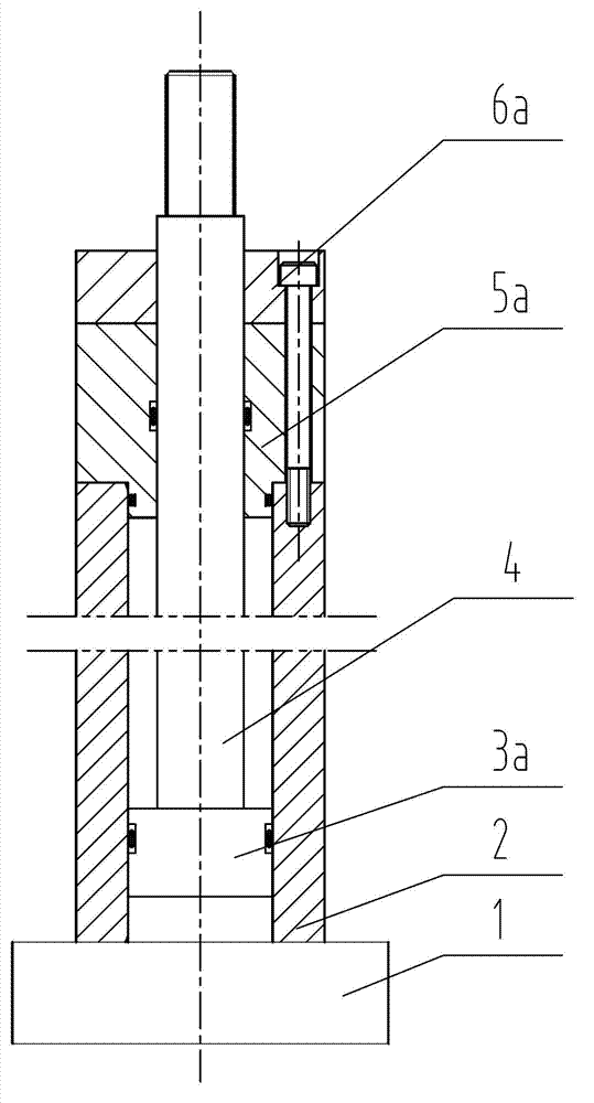
[0031] refer to Figure 5 , The anti-rotation hydraulic cylinder structure of this embodiment includes a hydraulic cylinder base 1, a hydraulic cylinder barrel 2, a piston 3, a piston rod 4, a hydraulic cylinder end cover 6 and seals between the components. The hydraulic cylinder base 1 is fixedly connected with the hydraulic cylinder barrel 2; the piston 3 is closely matched with the inner wall of the hydraulic cylinder barrel 2. An eccentric hole is arranged on the piston 3 to fix the piston rod 4 so that the piston rod 4 and the piston 3 are not on the same axis. The piston rod guide seat 5 is fixedly connected with the hydraulic cylinder barrel 2; the piston rod guide seat 5 is provided with a through hole to cooperate with the piston rod 4, and the hydraulic cylinder end cover 6 is fixedly connected with the hy...


PUM


Abstract

The invention discloses an anti-rotation structure and a method for a hydraulic cylinder. The anti-rotation structure for the hydraulic cylinder comprises a piston and a piston rod arranged in a main body of the closed hydraulic cylinder, one end of the piston rod is connected with the piston, and the other end of the piston rod penetrates out of the main body of the hydraulic cylinder. According to the method, one end of the piston rod is connected with a non-central part of the piston, and the axial lines of the piston rod and the piston are made in parallel. By improving the structure of the hydraulic cylinder, particularly adopting eccentric combination of the piston and the piston rod, the diameter of the tube of the hydraulic cylinder needs not to be increased to solve the problem of rotation of the traditional hydraulic cylinder in the piston rising process. Meanwhile, the problems of technical risks, significant cost increase and the like caused by adding a guide rod, changing the state of the piston rod, adopting a sleeve type cylinder and using other schemes can be avoided. Moreover, the device has the advantages of simple structure, convenience int operation, high reliability and low cost.

Description

technical field [0001] The invention relates to a lifting device for a hydraulic lifting impact test bench, in particular to a hydraulic cylinder anti-rotation structure and method, and belongs to the technical field of mechanical environmental testing. Background technique [0002] The impact test bench is a kind of mechanical environment test equipment, which is used to simulate the single or repeated impact environment of the tested piece during transportation or use, so as to assess the functional reliability and structural integrity of the tested piece in this environment. integrity. [0003] refer to figure 1 , The existing hydraulic lifting impact test bench is mainly composed of a base plate 13, a base 15, a damping device 14, a waveform generator 16, a guide column 19, a working table 17, a hydraulic lifting device 20, and a brake 18. Among them, the hydraulic lifting device is mainly composed of a hydraulic cylinder assembly, a pulley seat 25, a pulley 27, a wire...

Claims


Application Information

Patent Timeline
Patent Type & Authority Applications(China)
IPC IPC(8): F15B15/20F15B15/14G01M7/08
Inventor 吴国雄徐曼
Owner 苏州世力源科技有限公司
Why Eureka
Try Eureka