
Construction method applied to lifting platform in elevator shaft in constructional engineering

A technology of lifting platform and construction method, which is applied in construction, building structure, scaffolding supported by house structure, etc., can solve the problems of time-consuming and laborious installation work.

Inactive Publication Date: 2019-10-08
南通居者安建筑科学研究院有限公司 +2
View PDF8 Cites 2 Cited by
  • Summary
  • Abstract
  • Description
  • Claims
  • Application Information

AI Technical Summary

Problems solved by technology

[0004] The technical problem to be solved by the present invention is that when the existing hoisted triangular steel frame platform in the prior art needs to be lifted to adjust the position, it is necessary to use tower crane equipment to hoist and remove the supporting frame supporting the platform, and then use tower crane to hoist to a new floor Re-build the support frame at the working position, and the installation work is time-consuming and labor-intensive. The purpose is to provide a construction method applied to the elevator shaft lifting platform in construction engineering

Method used


Image

  • Construction method applied to lifting platform in elevator shaft in constructional engineering
  • Construction method applied to lifting platform in elevator shaft in constructional engineering
  • Construction method applied to lifting platform in elevator shaft in constructional engineering

Examples


Embodiment 1

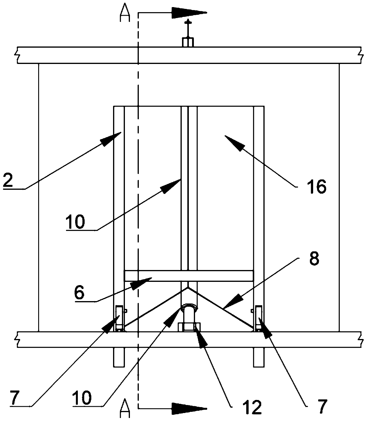
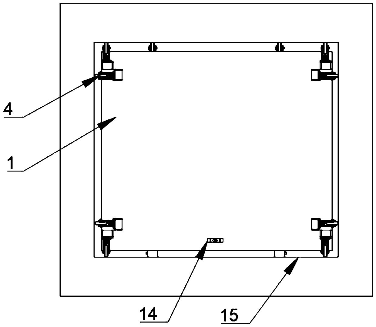
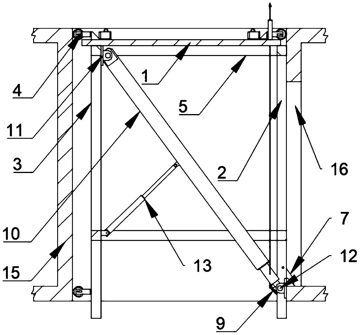
[0037] Such as Figure 1 to Figure 8 As shown, the present invention provides a kind of construction method that is applied to elevator shaft lifting platform in construction engineering, comprises the following steps:

[0038] Step 1. Build a workbench 1 in the elevator 15. The length and width of the workbench 1 are set according to the actual length and width of the elevator shaft 15. A gap needs to be reserved between the edge of the workbench 1 and the side wall of the elevator shaft 15 to prevent work. Platform 1 collides or gets stuck with the wall of elevator shaft 15 . The workbench 1 is lower than the top surface of the elevator shaft 15 , so that the side wall of the workbench 1 on the side away from the elevator shaft door opening 16 abuts against the wall of the elevator shaft 15 . The workbench 1 is composed of a rectangular frame welded by longitudinal beams and transverse beams and patterned steel plates, and the patterned steel plates are welded on the top of...

Embodiment 2

[0045] Such as figure 2 , image 3 with Figure 9 As shown, the present invention is a construction method applied to elevator shaft lifting platform in construction engineering. Compared with Embodiment 1, the difference between this embodiment and Embodiment 1 is that rubber rolling wheel assemblies 4 are fixedly connected around the workbench 1, and the rubber rolling wheels The wheel assembly 4 is in rolling connection with the walls of the elevator shaft 15 . The bottom of the second column 3 is fixedly connected with a rubber rolling wheel assembly 4, which is rollingly connected with the wall of the elevator shaft 15, and the rubber rolling wheel assembly 4 moves vertically up and down in the elevator shaft 15 following the workbench 1.

[0046] Specifically: the rubber roller assembly 4 includes a mounting plate 41, a support frame 42, a compression spring 46, a compression spring positioning shaft 45, a spring push plate 47, a rubber roller 43, a roller shaft pin 4...

Embodiment 3

[0049] Such as figure 1 , image 3 , Figure 5 to Figure 8 As shown, the present invention is a construction method applied to the elevator shaft lifting platform in construction engineering. The difference between this embodiment and Embodiment 1 is that the top of the shear key 7 passes through the cylindrical pin and the first column in the elongated hole. 2 Rotational connection, the shear key 7 is fixedly connected with a T-shaped tie rod 17 on the side away from the elevator shaft door hole 16. One end of the T-shaped tie rod 17 is threadedly connected with the shear key 7, and after the bottom of the shear force key 7 stretches out from the elongated hole, the other end of the T-shaped tie rod 17 is offset against the side wall of the first column 2. After the bottom of the shear key 7 retracts into the elongated hole, the other end of the T-shaped tie rod 17 is away from the side wall of the first column 2, and the T-shaped tie rod 17 is used to control the rotation ...


PUM


Abstract

The invention discloses a construction method applied to a lifting platform in an elevator shaft in constructional engineering. The construction method includes the following steps that a workbench iserected in the elevator shaft, the length and the width of the workbench are set according to the length and the width of the elevator shaft, and a gap is reserved between the edge of the workbench and the side wall of the elevator shaft; a supporting bracket is erected at the bottom of the workbench, and the height of the supporting bracket is larger than that of a door opening of the elevator shaft; shear keys are mounted on the lower portion of the supporting bracket, long holes for mounting of the shear keys are formed in the lower portion of the supporting bracket, and after stretching out, the bottoms of the shear keys abut against the bottom face of the door opening of the elevator shaft; and a lifting drive device is mounted between the workbench and the bottom face of the door opening of the elevator shaft, the top of the lifting drive device is fixedly connected with the bottom of the workbench, the bottom of the lifting drive device abuts against the bottom face of the dooropening of the elevator shaft, and the lifting drive device drives the workbench and the supporting bracket to vertically move in the elevator shaft up and down through telescopic motion. By means ofthe lifting platform, the erecting and lifting efficiency of an operating platform is improved.

Description

technical field [0001] The invention relates to the technical field of building construction, in particular to a construction method applied to an elevator shaft lifting platform in construction engineering. Background technique [0002] In the building high-rise construction process, the formwork support of the four walls of the elevator shaft of each floor in the room mainly adopts the method of erecting an operation platform. At present, there are mainly the following construction methods for the formwork support operation platform on the inner wall of the indoor elevator shaft: the first layer of vertical poles are directly landed to build the frame body operation platform layer by layer to carry out the formwork support construction work; The formwork support construction work is carried out on the triangular steel frame platform through hoisting by tower crane equipment; the formwork support construction work is carried out on the lifting steel platform, etc. [0003]...

Claims


Application Information

Patent Timeline
Patent Type & Authority Applications(China)
IPC IPC(8): E04G3/28E04G3/24
CPCE04G3/246E04G3/28E04G2003/286
Inventor 王萍其他发明人请求不公开姓名
Owner 南通居者安建筑科学研究院有限公司
Learn More