BIM-based automatic borehole perpendicularity monitoring method

An automatic monitoring and verticality technology, applied in surveying, earthwork drilling, wellbore/well components, etc., can solve the problems of construction process obstruction, lack of overall stability, water seepage in the hole, etc., to achieve novel and reasonable design, easy to promote Use, use with good effect

Active Publication Date: 2019-10-08
CHINA RAILWAY FIRST GRP CO LTD +1
View PDF15 Cites 3 Cited by
  • Summary
  • Abstract
  • Description
  • Claims
  • Application Information

AI Technical Summary

Problems solved by technology

[0002] The surrounding protection pile technology has been widely used in the construction process of foundation pit engineering, and its overall structure can better realize the function of retaining soil and waterproofing. If the construction hole position is inclined, the surrounding retaining pile system and the horizontal coordinates of the ground surface will be in a non-perpendicular state, and its overall stability will be lost, and its functionality will be greatly affected, and the expected stability of the foundation pit will not be achieved. For maintenance purposes, the retaining pile structure will not be able to achieve the expected function, posing a threat to the safety of the foundation pit project and hindering the next construction process
Existing methods for detecting the verticality of boreholes are to detect the verticality of boreholes by suspending ultrasonic detectors with pay-off ropes, or to detect the verticality of boreholes by emitting laser beams from laser detectors. The water seepage in the hole is serious, and the bottom of the hole cannot be seen clearly, and the laser beam emitted by the laser detector cannot play a role; the defense line carries the ultrasonic detector into the water, and the verticality of the defense line of the defense line cannot be guaranteed due to the buoyancy of the ultrasonic detector in the water. This leads to the failure of the method of detecting the verticality of the borehole by suspending the ultrasonic detector on the pay-off rope, making it difficult to accurately measure the verticality of the construction hole

Method used


Image

  • BIM-based automatic borehole perpendicularity monitoring method
  • BIM-based automatic borehole perpendicularity monitoring method
  • BIM-based automatic borehole perpendicularity monitoring method

Examples


Embodiment Construction

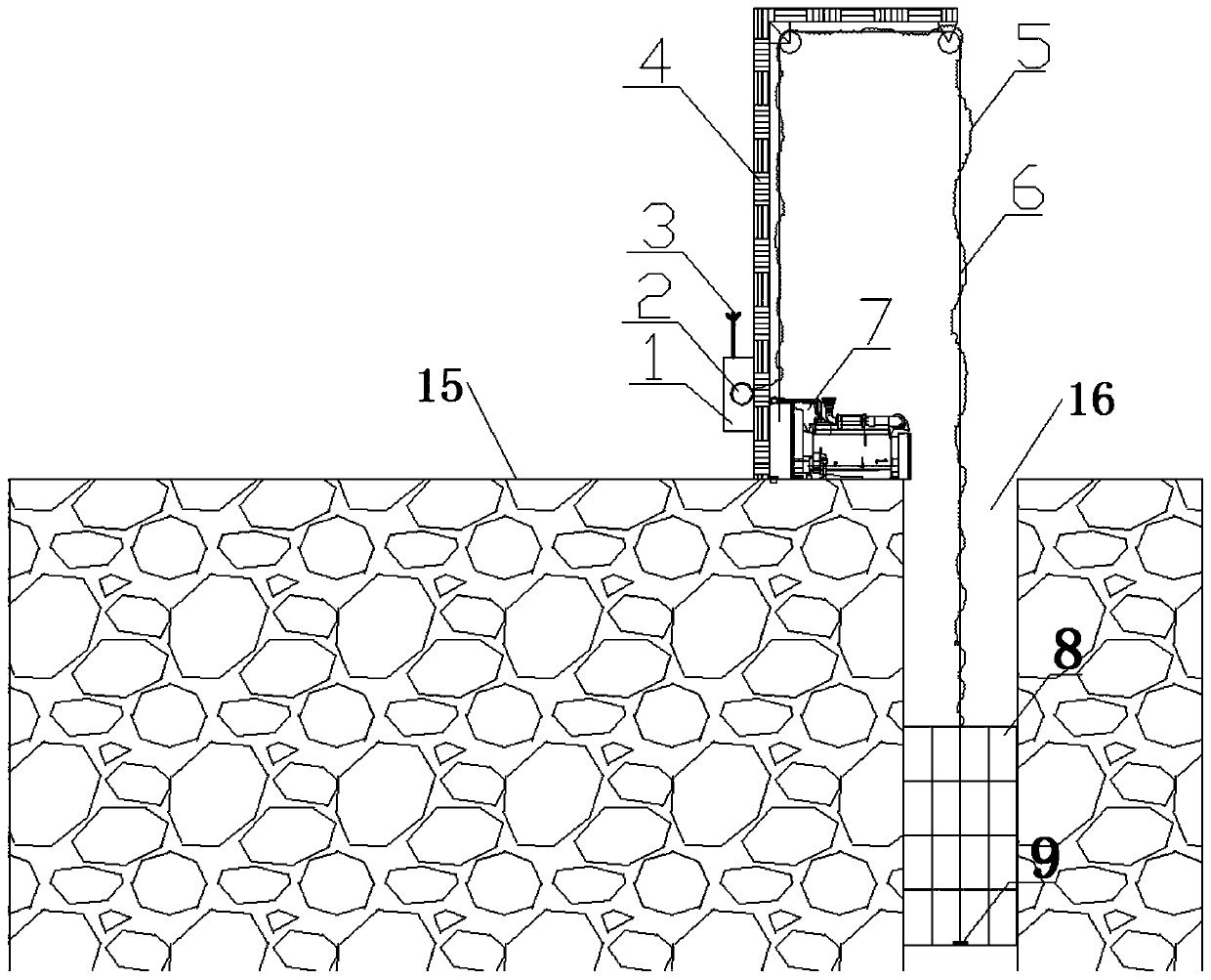
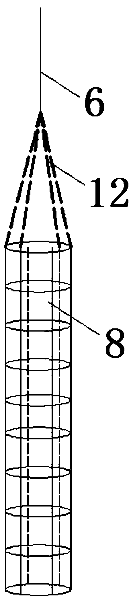
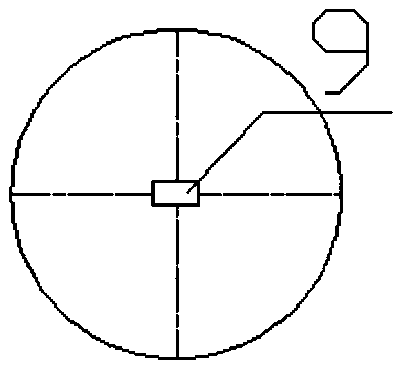
[0048] Such as Figure 1 to Figure 5 Shown, the present invention is based on the drilling verticality automatic monitoring method of BIM, comprises the following steps:

[0049] Step 1. Construct the drilling verticality detection mechanism, the process is as follows:

[0050] Step 101, install an inverted L-shaped support frame 4 on the side of the construction ground 15 at the top of the borehole 16, and the horizontal section of the inverted L-shaped support frame 4 is located in the center of the borehole 16 at the end of the vertical section of the inverted L-shaped support frame 4. On the axis, a pulley block is installed on the inner side of the inverted L-shaped support frame 4, and a crane 7 is installed on the construction ground 15, and the crane 7 is located on the inner side of the inverted L-shaped support frame 4;

[0051] It should be noted that the purpose of the horizontal section of the inverted L-shaped support frame 4 away from the end of the vertical se...


PUM


Abstract

The invention discloses a BIM-based automatic borehole perpendicularity monitoring method. The method comprises the steps of 1, constructing a borehole perpendicularity detection mechanism; 2, settinga unit declining distance of a tilt angle sensor; 3, enabling the tilt angle sensor to decline; 4, obtaining the declining data of the tilt angle sensor; 5, repeating the steps 3 and 4 for n times toobtain the tilt angle data of a reinforcement cage at n different height positions declining along the height direction of a borehole; 6, adjusting the position of the tilt angle sensor; 7, enablingthe tilt angle sensor to ascend; 8, obtaining the ascending data of the tilt angle sensor; 9, repeating the steps 7 and 8 for n times to obtain the tilt angle data of the reinforcement cage at n different height positions ascending along the height direction of the borehole, and calculating a measurement data deviation distance; 10, drawing an average deviation distance curve chart; and 11, establishing a BIM model of the borehole and visually monitoring the perpendicularity of the borehole. Through establishing the BIM model of the borehole and visually monitoring the perpendicularity of theborehole, the technicians are clear with the inclination states of the pile holes at a glance.

Description

technical field [0001] The invention belongs to the technical field of drilling verticality monitoring, and in particular relates to a BIM-based automatic monitoring method for drilling verticality. Background technique [0002] The surrounding protection pile technology has been widely used in the construction process of foundation pit engineering, and its overall structure can better realize the function of retaining soil and waterproofing. If the construction hole position is inclined, the surrounding retaining pile system and the horizontal coordinates of the ground surface will be in a non-perpendicular state, and its overall stability will be lost, and its functionality will be greatly affected, and the expected stability of the foundation pit will not be achieved. For maintenance purposes, the retaining pile structure will not be able to achieve the expected function, posing a threat to the safety of the foundation pit project and hindering the next construction proce...

Claims


Application Information

Patent Timeline
Patent Type & Authority Applications(China)
IPC IPC(8): E21B47/022
CPCE21B47/022
Inventor 李兴盛薛永锋姜谙男杜华林蒋腾飞高建新侯拉平李玉宏卢迪朱剑王传嘉沙千里张宏智王亮宋业华
Owner CHINA RAILWAY FIRST GRP CO LTD
Why Eureka
Try Eureka