System for exhaust gas recirculation tube alignment

An intake system, intake manifold technology, applied in exhaust gas recirculation, charging system, combustion air/combustion-air treatment, etc., can solve problems such as manufacturing delays

Pending Publication Date: 2019-10-08
FORD GLOBAL TECH LLC
View PDF1 Cites 0 Cited by
  • Summary
  • Abstract
  • Description
  • Claims
  • Application Information

AI Technical Summary

Problems solved by technology

This causes delays in manufacturing

Method used


Image

  • System for exhaust gas recirculation tube alignment
  • System for exhaust gas recirculation tube alignment
  • System for exhaust gas recirculation tube alignment

Examples


Embodiment Construction

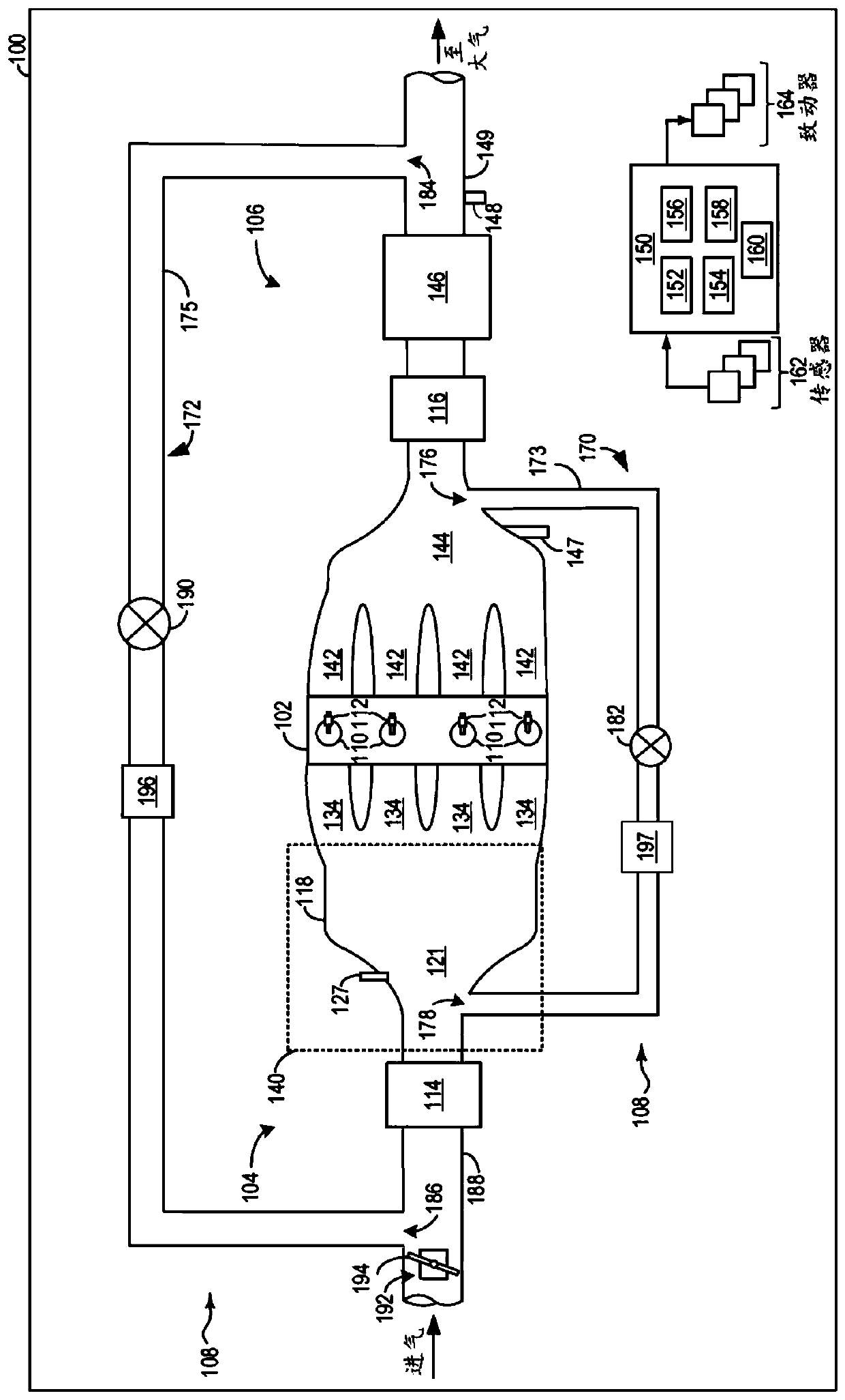
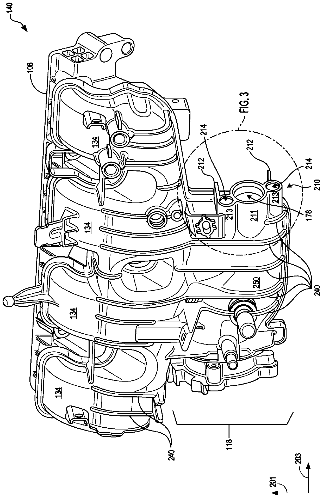
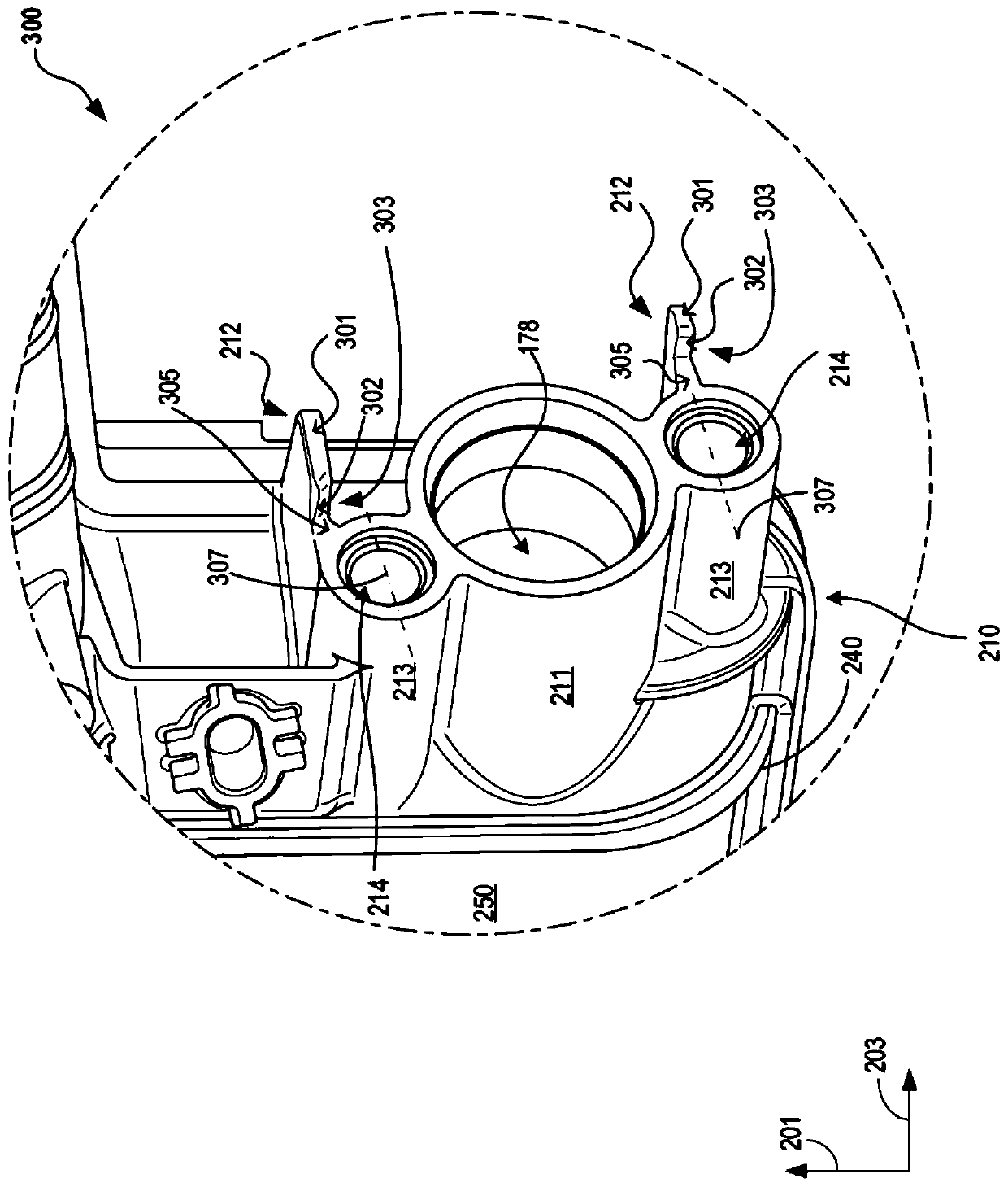
[0020] The following description pertains to integrating the exhaust gas recirculation (EGR) duct assembly with vehicle systems such as figure 1 The intake pipes of the vehicle system in the system) are installed together. Specifically, the following description relates to mounting features on the intake housing of a vehicle engine (which may be the intake manifold housing or the intake plenum housing) for assisting the integration of the EGR duct assembly with the intake air intake during the assembly process. Alignment and installation of gas housing. For example, during the manufacturing / development phase of a vehicle's lifecycle, particularly during the installation of the EGR pipe assembly to the intake housing, misalignment of the EGR pipe assembly to the intake housing may cause the EGR pipe assembly and intake manifold to Improper coupling between pipe shells. Therefore, a tight seal between the EGR pipe assembly and the intake housing may not be established. Theref...


PUM


Abstract

Systems are provided for aligning and assembling an exhaust gas recirculation (EGR) assembly with an engine intake housing. In one example, an intake system may include an EGR port housing for coupling the EGR assembly on an intake housing. The EGR port housing may include one or more alignment tabs on at least one side of the EGR port housing for aligning and guiding the EGR assembly during installation onto the intake housing.

Description

technical field [0001] The present description generally relates to an engine system having an exhaust gas recirculation system. Background technique [0002] Engine systems, including naturally aspirated and supercharged engines, utilize exhaust gas recirculation (EGR), in which a portion of exhaust gas is recirculated into the intake air, to reduce engine emissions and / or improve fuel economy. In supercharged engine systems that utilize a compressor in the intake system to provide the charge air charge, EGR can be delivered in a "high pressure" (HP) circuit or a "low pressure" (LP) circuit, where , EGR gas is taken before the turbine and injected after the compressor, and in the LP circuit, EGR gas is taken after the turbine and injected before the compressor. An engine system with EGR includes an EGR port in the intake pipe for admitting EGR gases. The intake housing typically includes a mounting surface for locating the EGR port and mounting the EGR duct assembly to th...

Claims


Application Information

Patent Timeline
Patent Type & Authority Applications(China)
IPC IPC(8): F02M26/04F02M26/09F02M26/17
CPCF02M26/04F02M26/09F02M26/17F02M26/05F02M26/12F02M35/10222F02M26/11F02M26/13F02M26/20
Inventor 桑德拉·奥西普基思·黑文杰弗里·斯坦卡维吉
Owner FORD GLOBAL TECH LLC
Why Eureka
Try Eureka