
A kind of decorative chandelier and its installation method

A technology for decorating a chandelier and an installation method, which is applied to lighting devices, lighting auxiliary devices, fixed lighting devices, etc., can solve the problems of large ceiling area in the hall, large number of crystal bead curtains, and long-time high-altitude work by installation staff.

Active Publication Date: 2021-07-02
深圳市晶艺装饰设计工程有限公司
View PDF7 Cites 0 Cited by
  • Summary
  • Abstract
  • Description
  • Claims
  • Application Information

AI Technical Summary

Problems solved by technology

[0003] However, due to the large area of ​​the hall ceiling and the huge perimeter of the light trough, the number of strings of crystal bead curtains that need to be hung is also very large, causing the installation staff to work at heights for a long time, which needs to be improved urgently

Method used


Image

  • A kind of decorative chandelier and its installation method
  • A kind of decorative chandelier and its installation method
  • A kind of decorative chandelier and its installation method

Examples


Embodiment 1

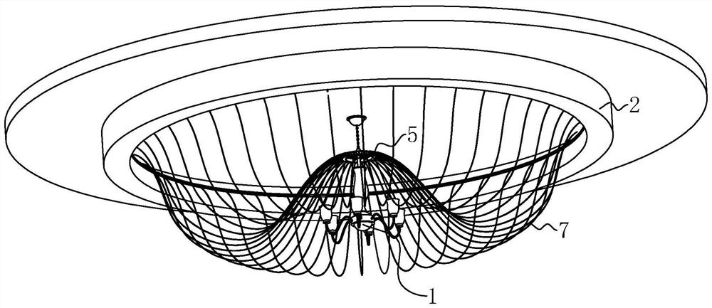
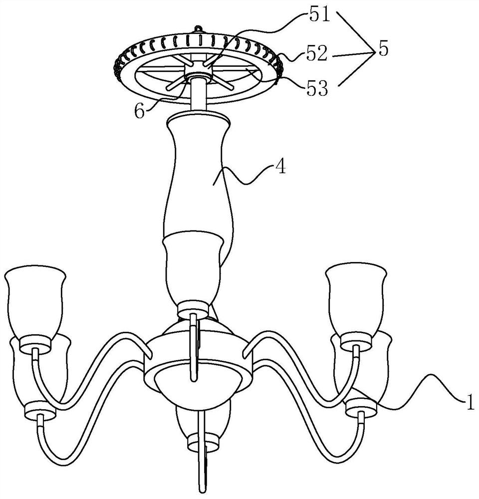
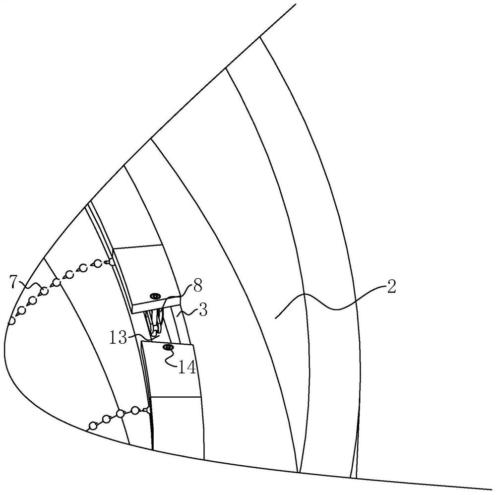
[0042] Embodiment one: refer to figure 1 with image 3 As shown, a decorative chandelier includes a chandelier 1 suspended on the ceiling, an annular light trough 2 is fixed on the edge of the ceiling, and a slide rail 3 is provided on the side of the light trough 2 close to the chandelier 1 . The chandelier 1 includes a mounting base 4, the mounting base 4 is covered with a mounting plate 5, and the mounting base 4 is fixed with a protruding ring 6 that conflicts with the lower end surface of the mounting plate 5, so that the mounting plate 5 can rotate around the chandelier 1. Bead curtain strings 7 are connected to the disk 5 at intervals in the circumferential direction, and the end of the bead curtain string 7 away from the installation disk 5 is connected to the slide rail 3 .

[0043] refer to figure 2 As shown, in order to reduce the overall quality of the chandelier 1 so that the chandelier 1 can be suspended and installed, the mounting plate 5 includes an inner ri...

Embodiment 2

[0047] Embodiment 2: A method for installing a decorative chandelier, combining Figure 5 As shown, the process is as follows:

[0048] Initial installation: Before hoisting the chandelier, first connect one end of the bead curtain string to the installation plate;

[0049]Entering the chain: insert the slide chain along the gap on the slide rail, and pass it out from the other end of the slide rail;

[0050] Hooking: Hook the sling on the chandelier mount to the sling on the ceiling;

[0051] Secondary installation: Embed the end of the bead curtain string away from the installation plate into the limit box, and then put a pin on the outlet of the limit box to realize the fixation of the bead curtain string and the limit box;

[0052] Chain running: The operator pulls the slide chain at the end of the uninstalled bead curtain string on the ground, so that the slide chain with the bead curtain string enters the slide rail, and at the same time continuously loads the bead cur...


PUM


Abstract

The invention discloses a decorative chandelier, which comprises: a chandelier suspended on the ceiling; a mounting plate that is rotatably assembled on the side of the chandelier close to the ceiling, the mounting plate is coaxially arranged with the chandelier, and beads are connected to the mounting plate at intervals in the circumferential direction. Curtain string: a ring-shaped slide rail set on the edge of the light groove, a bendable slide chain is installed inside the slide rail, and limit boxes are arranged on the slide chain at intervals, and one end of the bead curtain string is fixed at the limit In the box, the other end is connected with the installation plate; there is a gap on the slide rail, so that the slide chain can be inserted into the slide rail with the bead curtain string; and, the end of the slide rail near the gap is equipped with a The limit piece fixedly connected to the end of the slide chain, the operator can install the bead curtain string into the slide chain on the ground, and then put the slide chain together with the bead curtain string into the slide rail, after the bead curtain string is installed, pass the limit The bit parts can fix the slide chain on the slide rail, and finally realize the fixing of the bead curtain string, thereby facilitating the installation of the bead curtain string.

Description

technical field [0001] The invention relates to the field of interior decoration, in particular to a decorative chandelier and an installation method thereof. Background technique [0002] In the center of the ceiling in the lobby of some luxury hotels, a huge chandelier is usually installed. In order to increase the brightness of the hall, a light trough is set on the edge of the ceiling, and the ceiling area of ​​the hall is large, resulting in too much distance between the light trough and the chandelier. Large, in order to decorate this distance, one of the current arrangements is to hang strings of crystal bead curtains between the chandelier and the light groove. [0003] However, due to the large area of ​​the hall ceiling and the huge perimeter of the light trough, the number of strings of crystal bead curtains that need to be hung is also very large, resulting in long-term high-altitude work for installation staff, which needs to be improved urgently. Contents of ...

Claims


Application Information

Patent Timeline
Patent Type & Authority Patents(China)
IPC IPC(8): F21S8/06F21V21/02F21V17/08
CPCF21S8/063F21V17/08F21V21/02
Inventor 罗全芳
Owner 深圳市晶艺装饰设计工程有限公司
Learn More