
Customized electrothermal film

An electric heating film, the fourth technology, applied in the field of electric floor heating, can solve the problems of different power density, potential safety hazards of electric heating film, inability to adapt, etc., and achieve the effect of avoiding secondary processing, significant economic benefits, and stable electrical parameters

Pending Publication Date: 2019-10-08
上海德赟电热材料科技有限公司
View PDF0 Cites 0 Cited by
  • Summary
  • Abstract
  • Description
  • Claims
  • Application Information

AI Technical Summary

Problems solved by technology

[0002] Electric heating film products have been widely used in the field of electric floor heating, and basically adopt a product model of fixed width, fixed power density, and length cut according to a fixed modulus. This model has shortcomings. First, it encounters irregular room shapes. The shape of the fixed width and fixed length modulus cannot adapt; secondly, the latitude of the room is different, the thermal enclosure structure of the room is different, the required power density is different, and the power required by different parts in the same room The density is also different, so the mode of fixed power density cannot be adapted; the third is that the length of the electrothermal film is cut on site, and the cut electrothermal film conductive copper foil needs to be jointed and packaged on site during construction. During the application, due to the uneven skills of the construction personnel, the quality of the joints cannot be guaranteed, and the site does not have the conditions to test the waterproof, sealing, insulation and joint reliability of the cut electric heating film, so it leaves a safety gap for the electric heating film. Hidden dangers, and the temporary joints and packaging of the electric heating film are buried below the ground together with the electric heating film, once a failure occurs, it cannot be repaired

Method used


Image

  • Customized electrothermal film

Examples


Embodiment Construction

[0040] The specific implementation manners of the present invention will be further described below in conjunction with the drawings and examples. The following examples are only used to illustrate the technical solution of the present invention more clearly, but not to limit the protection scope of the present invention.

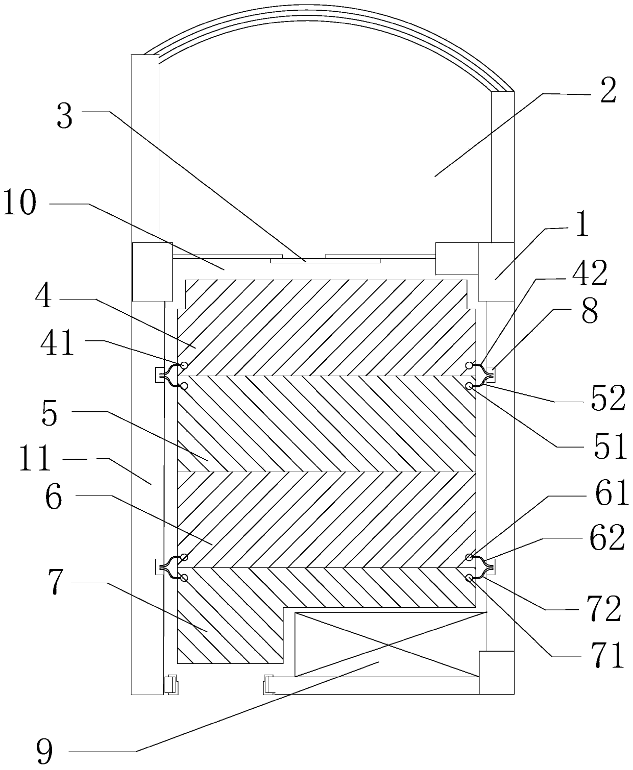
[0041] Such as figure 1 As shown, the present embodiment provides a customized electric heating film installed on the ground 10 of the room 1, the room 1 is equipped with a floor-to-ceiling glass window 3, and there is a balcony 2 outside the floor-to-ceiling glass window 3; including the first electric heating film 4, the second Two electrothermal films 5, third electrothermal films 6, fourth electrothermal films 7, four junction boxes 8, two first leads 42, two second leads 52, two third leads 62 and two fourth leads 72 ; The first electrothermal film 4, the second electrothermal film 5, the third electrothermal film 6 and the fourth electrothermal film ...


PUM


Abstract

The invention discloses a customized electrothermal film. The customized electrothermal film is installed on the floor of a room, the room is equipped with a floor-to-ceiling glass window, and a balcony is outside the floor-to-ceiling glass window. The customized electrothermal film comprises a first electrothermal film body, a second electrothermal film body, a third electrothermal film body, a fourth electrothermal film body, four junction boxes, two first lead wires, two second lead wires, two third lead wires and two fourth lead wires, wherein the first electrothermal film body, the secondelectrothermal film body, the third electrothermal film body and the fourth electrothermal film body are sequentially laid on the floor from the floor-to-ceiling glass window inwards; the power density of the second electrothermal film body, the third electrothermal film body and the fourth electrothermal film body decreases gradually; and the power density of the first electrothermal film body is 110-130% of the average power density of the first electrothermal film body, the second electrothermal film body, the third electrothermal film body and the fourth electrothermal film body. The customized electrothermal film, including the lead wires, is integrally insulated, sealed and waterproof, and has stable electrical parameters and high security. Direct construction and installation are carried out on site, the hidden danger of secondary machining is avoided, and the customized electrothermal film has significant economic benefits.

Description

technical field [0001] The invention relates to the field of electric floor heating, in particular to a customized electric heating film. Background technique [0002] Electric heating film products have been widely used in the field of electric floor heating, and basically adopt a product model of fixed width, fixed power density, and length cut according to a fixed modulus. This model has shortcomings. First, it encounters irregular room shapes. The shape of the fixed width and fixed length modulus cannot adapt; secondly, the latitude of the room is different, the thermal enclosure structure of the room is different, the required power density is different, and the power required by different parts in the same room The density is also different, so the mode of fixed power density cannot be adapted; the third is that the length of the electrothermal film is cut on site, and the cut electrothermal film conductive copper foil needs to be jointed and packaged on site during co...

Claims


Application Information

Patent Timeline
Patent Type & Authority Applications(China)
IPC IPC(8): F24D13/02H05B3/02H05B3/04H05B3/34
CPCF24D13/024H05B3/02H05B3/04H05B3/34Y02B30/00
Inventor 徐秉绶
Owner 上海德赟电热材料科技有限公司
Learn More