Wire energy-saving blow-drying device

A wire rod and support frame technology, applied in the field of wire rod energy-saving blow-drying device, can solve the problems of time-consuming, labor-intensive, large air output, and inability to effectively remove liquid residues

Pending Publication Date: 2019-10-08
威海邦德散热系统股份有限公司
View PDF0 Cites 1 Cited by
  • Summary
  • Abstract
  • Description
  • Claims
  • Application Information

AI Technical Summary

Problems solved by technology

At present, most of the air knives used in the market are "one" slotted air knives, which require the air source pressure to be greater than 0.7mpa. The air output is large but the pressure at the air outlet is weak, which cannot effectively remove the liquid residue.
The same wire processing equipment needs to produce multiple specifications of wire rods, and the replacement and adjustment of the "one" slotted air knife is time-consuming and laborious
The production speed of wire rod products is extremely fast and can reach more than 120m / min. The "one" slotted air knife cannot meet the needs of high-speed products, which affects efficiency and product quality.

Method used


Image

  • Wire energy-saving blow-drying device
  • Wire energy-saving blow-drying device
  • Wire energy-saving blow-drying device

Examples


Embodiment Construction

[0021] Below in conjunction with accompanying drawing, the present invention is further described:

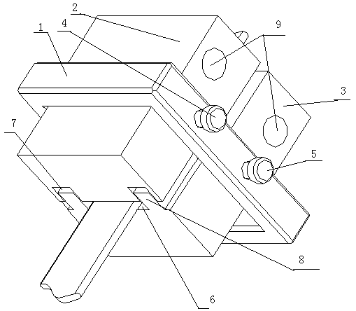
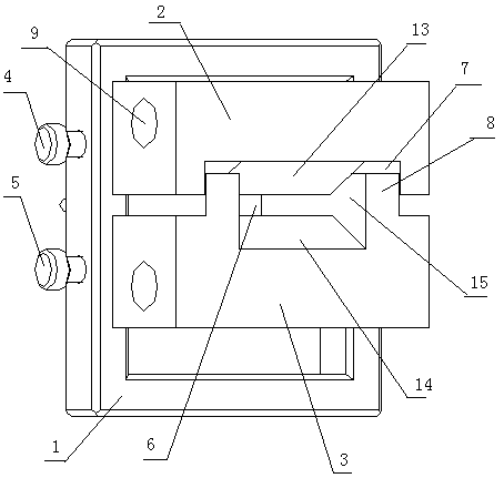
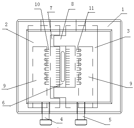
[0022]As shown in the accompanying drawings, an energy-saving blow-drying device for wire is characterized in that the device is composed of a support frame 1, an upper module 2, a lower module 3, an upper locking bolt 4 and a lower locking bolt 5, and the supporting frame 1 is set as a square, and the upper module 2 and the lower module 3 are arranged in the square support block, and the opening gap between the upper module 2 and the lower module 3 is set as the product passing hole 6, and the upper module 2 and the lower module 3 The front side or rear side of the upper module 2 and the lower module 3 are in contact with the support frame 1, and the rear side or front side of the upper module 2 and the lower module 3 are locked and connected with the support frame 1 through the upper locking bolt 4 and the lower locking bolt 5 respectively. The upper locking bolt 4 passes thr...


PUM


Abstract

The invention relates to the technical field of on-line blow-drying equipment, in particular to a wire energy-saving blow-drying device. The device is characterized in that the device is composed of asupport frame, an upper module, a lower module, an upper locking bolt and a lower locking bolt; the support frame is square; the square support frame is internally provided with the upper module andthe lower module; an opening gap between the upper module and the lower module is set as a product via hole; the rear side surfaces or the front side surfaces of the upper module and the lower moduleare locked and connected with the support frame through the upper locking bolt and the lower locking bolt correspondingly; the front side and the rear side of the lower end surface of the upper moduleare provided with strip-shaped grooves correspondingly; the front side and the rear side of the upper end surface of the lower module are provided with strip-shaped bosses correspondingly; the left end portions of the front side surfaces or the rear side surfaces of the upper module and the lower module are provided with air inlet blind holes; upper air outlets are formed in the hole wall of theair inlet blind hole of the upper module; and lower air outlets are formed in the hole wall of the air inlet blind hole of the lower module. The device has the advantages of simple structure, convenient use, good blow-drying effect, high drying efficiency, low energy consumption and the like.

Description

technical field [0001] The invention relates to the technical field of online drying equipment, in particular to an energy-saving wire drying device with simple structure, convenient use, good drying effect, high drying efficiency and reduced energy consumption. Background technique [0002] As we all know, the pipes in chemical industry, plumbing, air conditioning, etc. have different shapes, such as flat tubes and rectangular tubes, etc. The wires and cables used in the electromechanical industry have high requirements for appearance. There will be residue after contact with the liquid. If it is not removed in time, it will leave stains and cause corrosion and other defects. Therefore, an online drying device is required to remove the liquid residue. At present, most of the air knives used in the market are "one" slotted air knives, which require the air source pressure to be greater than 0.7mpa. The air output is large but the pressure at the air outlet is weak, which can...

Claims


Application Information

Patent Timeline
Patent Type & Authority Applications(China)
IPC IPC(8): F26B21/00
CPCF26B21/004
Inventor 张磊吴国良杨振兴
Owner 威海邦德散热系统股份有限公司
Why Eureka
Try Eureka