
Earthquake monitor for mine region

A monitor and regional technology, applied in the field of seismic monitors in mining areas, can solve problems such as poor performance, inability to release well locks, and inability to take out monitoring equipment, achieving the effect of ingenious conception and simple structure

Inactive Publication Date: 2019-10-08
EARTHQUAKE ADMINISTRATION OF BEIJING MUNICIPALITY
View PDF6 Cites 5 Cited by
  • Summary
  • Abstract
  • Description
  • Claims
  • Application Information

AI Technical Summary

Problems solved by technology

[0002] Surface and shallow seismic monitoring has been greatly affected in mining areas due to surface mining and underground mining. In order to carry out effective base monitoring in mining areas, underground seismic monitoring is generally used, and the seismometer is placed in the well and directly connected to the bedrock of the observation well. Rigidly connected together, the existing well lock fixing device cannot release the well lock when the power is cut off, so that the underground monitoring equipment cannot be taken out. At the same time, it is difficult to level and adjust the seismometer because it is placed underground. If the seismometer works at a tilt of 2°, the performance will be poor, and it will not be able to monitor effectively and meet the actual needs. Therefore, we have invented a seismic monitor for mining areas.

Method used


Image

  • Earthquake monitor for mine region
  • Earthquake monitor for mine region
  • Earthquake monitor for mine region

Examples


Embodiment Construction

[0014] In order to make the purpose, technical solutions and advantages of the embodiments of the present invention clearer, the technical solutions in the embodiments of the present invention will be clearly and completely described below in conjunction with the drawings in the embodiments of the present invention. Obviously, the described embodiments It is a part of embodiments of the present invention, but not all embodiments. Based on the embodiments of the present invention, all other embodiments obtained by persons of ordinary skill in the art without creative efforts fall within the protection scope of the present invention.

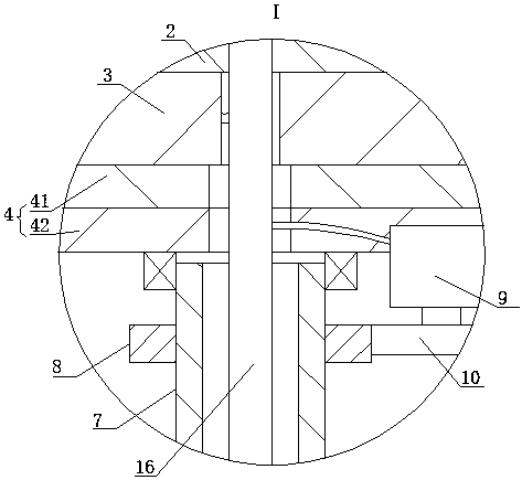
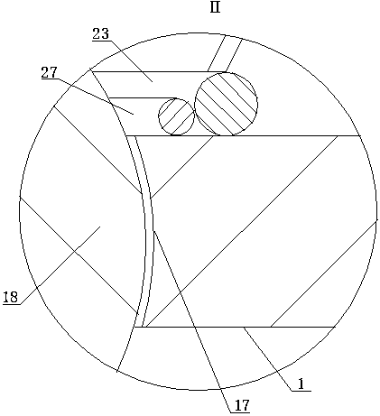
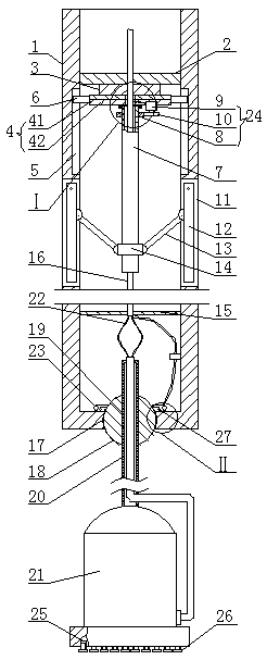
[0015] A kind of earthquake monitoring instrument in mining area, as shown in the figure, includes a standpipe 1, the upper part of the standpipe 1 is provided with an upper annular partition 2, and the bottom side of the upper annular partition 2 is fixedly installed with a ring electromagnet 3, and the ring electromagnet 3 The bottom side of the...


PUM


Abstract

The invention relates to an earthquake monitor for a mine region. The monitor comprises a vertical tube, an upper annular separator plate is arranged in the upper portion of the vertical tube, an annular electromagnet is fixedly mounted in the bottom side of the upper annular separator plate, an annular metal plate is arranged in the bottom side of the annular electromagnet, the bottom side of theannular electromagnet can electromagnetically attracts the top side the annular metal plate, bar-shaped chutes in left-right symmetry are formed in the upper portion of the inner wall of the verticaltube, slide blocks are arranged in the bar-shaped chutes respectively, can slide up and down along the corresponding bar-shaped chutes, and are fixedly connected with the annular metal plate, the bottom side of the annular metal plate is in bearing connection with the upper end of an outside threaded tube, a driver which can enable the outside threaded tube to rotate is fixedly mounted in the bottom side of the annular metal plate, bar-shaped through grooves in left and right symmetry are formed in the middle portion of the periphery of the vertical tube, the upper portions of the bar-shapedthrough grooves are hinged to the upper ends of support rods respectively, the inner upper portion of each support rod is hinged to one end of the upper end of one corresponding connecting rod, and anut is mounted in the lower end of the periphery of the outside threaded tube in a treaded way. The earthquake monitor for the mine region is simple in structure and ingenious in conception.

Description

technical field [0001] The invention belongs to the field of monitoring instruments, in particular to an earthquake monitoring instrument for mining areas. Background technique [0002] Surface and shallow seismic monitoring has been greatly affected in mining areas due to surface mining and underground mining. In order to conduct effective base monitoring in mining areas, underground seismic monitoring is generally used, and the seismometer is placed in the well and directly connected to the bedrock of the observation well. Rigidly connected together, the existing well lock fixing device cannot release the well lock when the power is cut off, so that the underground monitoring equipment cannot be taken out. At the same time, it is difficult to level and adjust the seismometer because it is placed underground If the seismometer works at an inclination of 2°, its performance will deteriorate, and it will not be able to perform effective monitoring and meet the actual needs. T...

Claims


Application Information

Patent Timeline
Patent Type & Authority Applications(China)
IPC IPC(8): G01V1/52G01V1/00G01V1/20G01V1/16
CPCG01V1/52G01V1/201G01V1/168G01V2001/526G01V2210/1429G01V1/01
Inventor 王飞刘博谭庆全
Owner EARTHQUAKE ADMINISTRATION OF BEIJING MUNICIPALITY
Learn More