Gate over-flow calculation method

A calculation method and over-flow technology, applied in the directions of calculation, computer-aided design, design optimization/simulation, etc., can solve the problem of time-consuming and labor-intensive process of gate over-flow, and achieve the effect of low cost and high precision

Active Publication Date: 2019-10-08
CHINA INST OF WATER RESOURCES & HYDROPOWER RES
View PDF6 Cites 0 Cited by
  • Summary
  • Abstract
  • Description
  • Claims
  • Application Information

AI Technical Summary

Problems solved by technology

[0003] Aiming at the above-mentioned deficiencies in the prior art, the method for calculating gate overflow provided by the present invention solves the problem of time-consuming and laborious determination of gate overflow in the existing method

Method used


Image

  • Gate over-flow calculation method
  • Gate over-flow calculation method
  • Gate over-flow calculation method

Examples


specific example

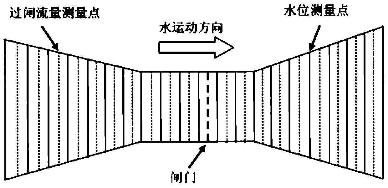
[0116] In this example, the above method was applied to Dali Village in Luquan, Yehe Irrigation Area, Hebei Province as a test site. See Figure 4 , where the slope on both sides of the channel is 10°, and the cross-section of the channel is plastered with cement slurry and masonry. Therefore, according to the roughness value table in hydraulics, the roughness value is taken as 0.025. Based on the geometric parameters of these channels, a magnetostrictive water level gauge with an accuracy of 1mm is used to measure and obtain the upstream and downstream water level values ​​of multiple groups of gates and calculate the flowmeter. / s) to obtain the flow value at the downstream measuring point (Table 1). From the data in the table, it can be seen that there is an excellent fitting degree between the simulated and measured upstream and downstream water levels (the maximum average relative error value is less than 1%), thus accurate flow through the gate can be obtained.

[0117...


PUM


Abstract

The invention discloses a gate excess flow calculation method. By presetting a brake-passing flow Q, the simulation values of the front and rear water levels of the gate are solved through a hydrodynamic partial differential equation set by means of the actual measurement values of the front and rear water levels of the gate. The water level error between the simulation values and the actual measurement values is compared with a preset threshold value, then the preset gate-passing flow Q and the preset water level error are adjusted to be within the preset threshold value range, and the current preset gate-passing flow serves as accurate gate-passing flow. Compared with an existing gate overflow measurement method, the method has the remarkable advantages of being low in cost and high in precision.

Description

technical field [0001] The invention belongs to the technical field of flow measurement of water conservancy gates, and in particular relates to a method for calculating the flow rate of a gate. Background technique [0002] Accurately knowing the flow through the gate is an important task in the management of watersheds or irrigation areas. Using the water level before and after the gate to calculate the flow through the gate of the river or channel is a common method of flow acquisition. However, these methods are based on basic or modified hydraulic formulas, which are semi-theoretical-semi-empirical formulas, and there are empirical undetermined parameters such as shrinkage coefficients with unknown physical meanings. Even if it takes time and effort to calibrate this parameter, its value will still change with the change of the water level before and after the gate, rather than a fixed value, which leads to the disadvantages of poor accuracy and high application cost of...

Claims


Application Information

Patent Timeline
IPC IPC(8): G06F17/50
CPCG06F30/20
Inventor 章少辉李益农戴玮陈皓锐白美健史源任贺靖
Owner CHINA INST OF WATER RESOURCES & HYDROPOWER RES
Why Eureka
Try Eureka