Laser ranging module and ranging method

A laser ranging and laser technology, which is used in measurement devices, radio wave measurement systems, instruments, etc., can solve the problem that the ranging device cannot meet the accuracy requirements of the print head, the measurement accuracy and cost are high, and the equipment is not easy to install and print. First-class problem, to achieve the effect of increasing application scalability, realizing automatic zero adjustment function, and low-cost installation

Pending Publication Date: 2019-01-04
哈尔滨拓思科技有限公司
View PDF7 Cites 1 Cited by
  • Summary
  • Abstract
  • Description
  • Claims
  • Application Information

AI Technical Summary

Problems solved by technology

[0002] Most of the existing 3D printers use the method of downward zero adjustment, but the current zero adjustment effect is not ideal. Fused deposition rapid prototyping (FDM) is one of the main 3D printing technologies. FDM technology, also known as hot melt Stacking technology, this technology is to heat and melt the hot-melt filament and extrude it from the nozzle, deposit it on the printing platform or the previous layer of solidified material, when the temperature is lower than the solidification temperature of the filament, it will start to solidify and form, and finally print Therefore, the printing of the first layer of the model directly affects the modeling effect of the subsequent model, and the coordination of the distance between the printing extrusion head and the printing platform and the amount of extrusion material (the layer height of the first layer of printing) directly affects the first layer. layer printing effect, so the machine's zero-adjustment technology is very important. For the case of upward zero-adjustment, that is, the Z-axis limit switch Z-axis maximum value, an important step to realize the automatic zero-adjustment function is close-range accurate measurement. The demand for accuracy and cost is high. At present, most of the existing methods are ultrasonic and laser radar methods. However, the high-precision cost of this distance measuring instrument is very high, and the low-cost distance measuring device cannot meet the accuracy requirements of the print head. And most of the equipment is not easy to install to the print head

Method used


Image

  • Laser ranging module and ranging method
  • Laser ranging module and ranging method
  • Laser ranging module and ranging method

Examples


specific Embodiment approach 1

[0028] Specific embodiments one, the following will be combined with the attached Figure 1-5 , the present invention is described in detail:

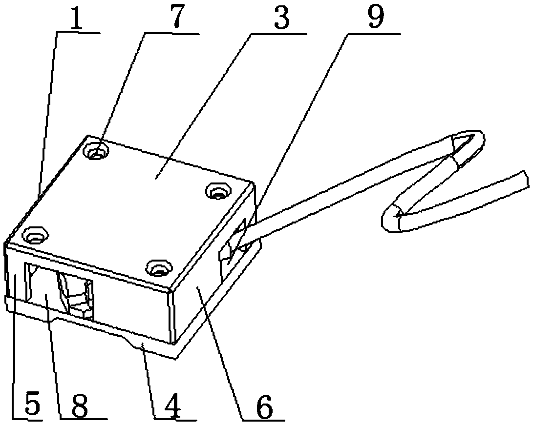
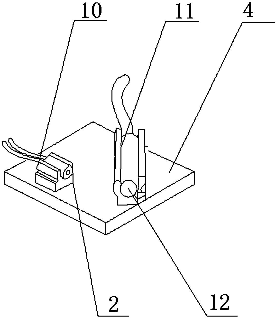
[0029] A kind of laser ranging module of the present invention is to solve the above-mentioned problem and adopts the technical scheme that comprises laser ranging box 1 and laser ranging device 2, and laser ranging box 1 is a square box structure, and laser ranging device 2 Installed inside the laser ranging box 1, the laser ranging box 1 includes an upper shell 3, a lower shell 4, a first support plate 5 and a second support plate 6, the upper shell 3 is arranged on the lower shell 4 Above, the surrounding area between the upper shell plate 3 and the lower shell plate 4 is supported by the first support plate 5 and the second support plate 6, four screw holes 7 are processed at the four corners of the upper shell plate 3, the first The left side of the support plate 5 is provided with a distance measuring hole 8, and the right side ...

specific Embodiment approach 2

[0030] Specific implementation mode two, the following will be combined with the attached Figure 1-5 , the present invention is described in detail:

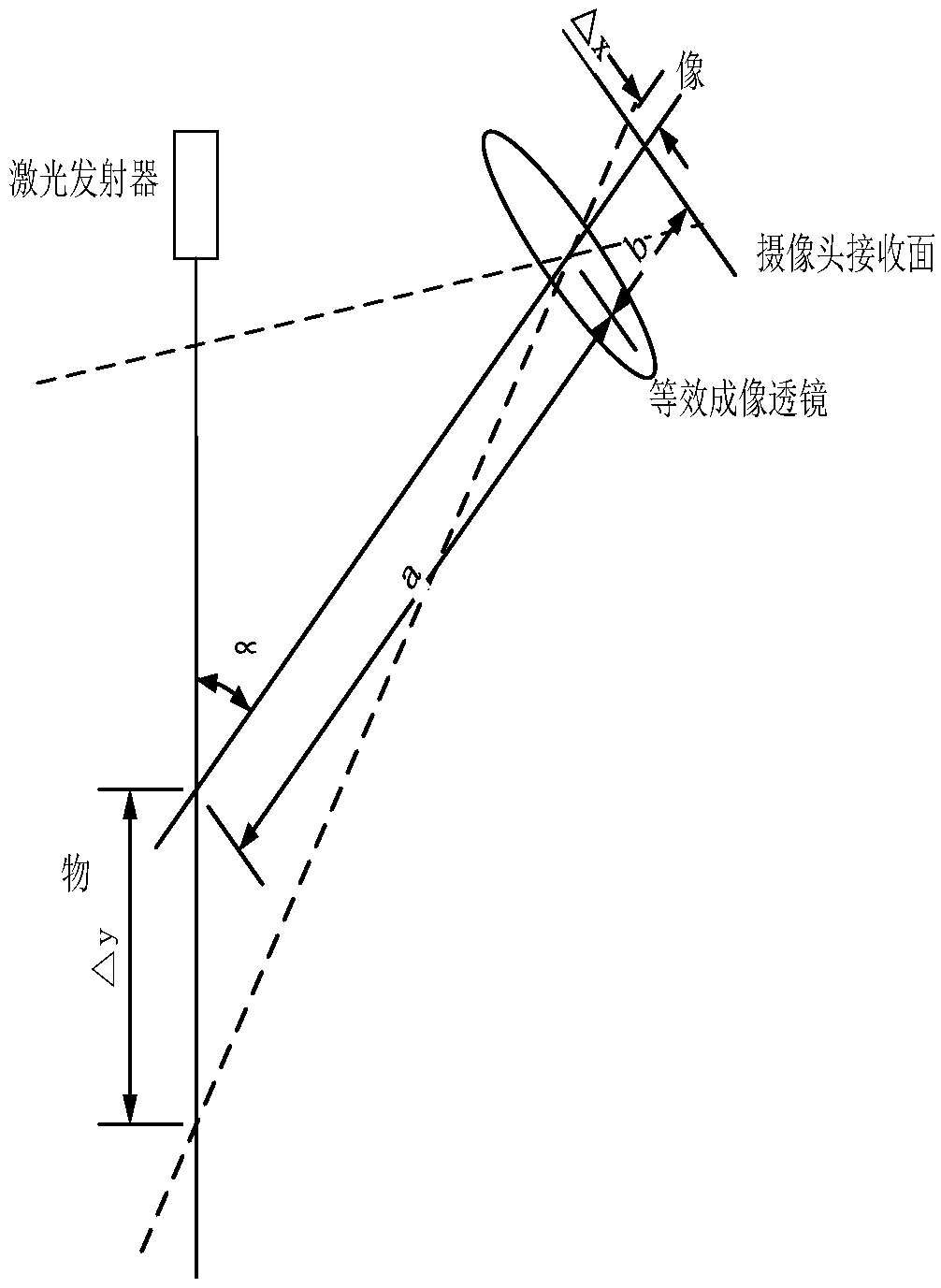
[0031] The laser 10 is perpendicular to the platform, that is, the angle between the emitted laser ray axis and the imaging axis of the camera 11 is α,

[0032] Step a, record the movement of the object along the direction of the laser ray as shown in Δy;

[0033] Step b, record that the image of the object in the receiving surface of the camera 11 moves Δx accordingly;

[0034] Step c, if the object moves along the direction of the laser ray as shown in the figure Δy, the image of the object in the receiving surface of the camera 11 will move Δx accordingly. Generally, the measurement range of the laser ranging is much larger than the effective length of the receiving surface of the camera 11, so the lens system The resulting image is a reduced image, and the relationship between the displacement of the object and the displa...

specific Embodiment approach 3

[0037] Specific implementation mode three, the following will be combined with the attached Figure 1-5 , the present invention is described in detail:

[0038] A laser ranging method,

[0039] Step 1. Obtain the displacement relationship between the displacement of the printer object and the image;

[0040] Step 2. Obtain the Z-axis coordinate position of the printing platform in the current coordinate system;

[0041] Step 3. When the upper computer control program wants to print and transmit the print file, it performs Z-axis coordinate processing, and the upper computer control program processes the print file according to the height of the platform and then transmits it to the printer;

[0042] Step 4, the printer prints the received file to realize printing on the printing platform;

[0043]The host computer control program will realize the semi-automatic calibration of the laser module. First, let the extrusion head and the laser module installed on the extrusion hea...


PUM


Abstract

The invention provides a laser ranging module and ranging method, belongs to the technical field of 3D printers, and aims at solving the problems that a ranging device cannot meet the precision requirement of a printing head and most of the equipment is too large to fit the printing head easily. The laser ranging method comprises the steps: 1, the displacement relation expression between the displacement and the image of the printer object is obtained; 2, the Z-axis coordinate position of the printing platform in the current coordinate system is obtained, 3, when the upper computer control program requires to print and transmit a printing file, Z-axis coordinate processing is performed on the printing file; and 4, the printer prints the received file and realizes printing on the printing platform. The laser ranging module is installed on the extrusion head of the printer, the laser ranging module has a laser, a camera and a light filter, the laser can emit light beams, the light beamsemitted by the laser directly irradiate to the printing platform of the printer, the camera can capture the light spots irradiated on the printing platform by the laser, and the light filter is installed on the camera so as to ensure the precision requirement of the printing head.

Description

technical field [0001] The invention relates to the technical field of 3D printers, in particular to a laser ranging module and a ranging method. Background technique [0002] Most of the existing 3D printers use the method of downward zero adjustment, but the current zero adjustment effect is not ideal. Fused deposition rapid prototyping (FDM) is one of the main 3D printing technologies. FDM technology, also known as hot melt Stacking technology, this technology is to heat and melt the hot-melt filament and extrude it from the nozzle, deposit it on the printing platform or the previous layer of solidified material, when the temperature is lower than the solidification temperature of the filament, it will start to solidify and form, and finally print Therefore, the printing of the first layer of the model directly affects the modeling effect of the subsequent model, and the coordination of the distance between the printing extrusion head and the printing platform and the amo...

Claims


Application Information

Patent Timeline
Patent Type & Authority Applications(China)
IPC IPC(8): G01S17/08
CPCG01S17/08
Inventor 廖雪飞杨佳锷林伟阳杨佳喆王雨佳
Owner 哈尔滨拓思科技有限公司
Why Eureka
Try Eureka