
Channel scanning device in satellite television system and channel scanning method

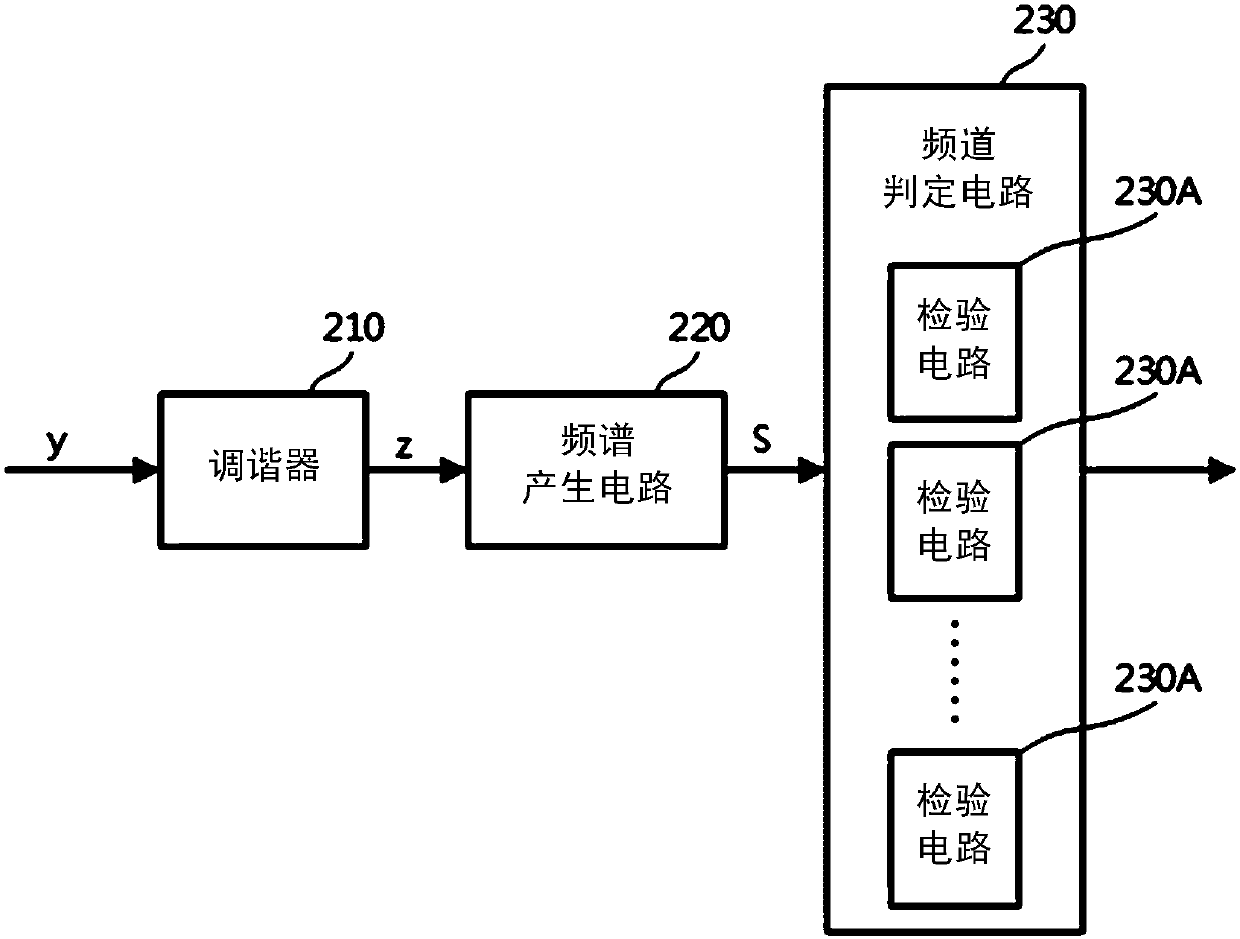
A satellite TV and scanning device technology, applied in the field of channel scanning technology, can solve the problem that the channel judging circuit 230 cannot judge the left and right boundaries of TV channels, etc.

Inactive Publication Date: 2019-10-08
MSTAR SEMICON INC
View PDF9 Cites 0 Cited by
  • Summary
  • Abstract
  • Description
  • Claims
  • Application Information

AI Technical Summary

Problems solved by technology

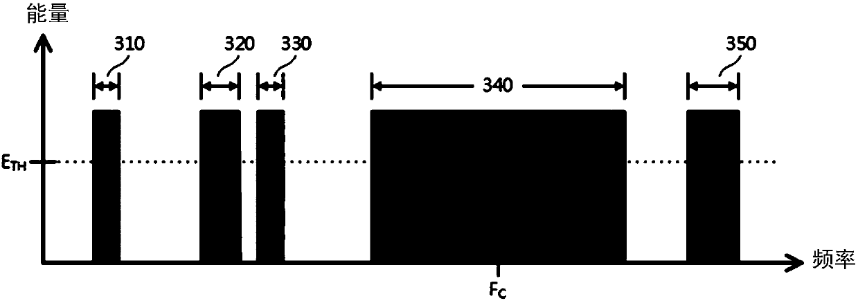
Compare Figure 3A and Figure 3B It can be seen that the problem of spectral distortion will greatly increase the difficulty of channel scanning
More specifically, after finding out the energy is higher than the preset threshold value E TH After the frequency segment, the channel determination circuit 230 cannot directly determine the left and right boundaries of the segment where the TV channel is located.

Method used


Image

  • Channel scanning device in satellite television system and channel scanning method
  • Channel scanning device in satellite television system and channel scanning method
  • Channel scanning device in satellite television system and channel scanning method

Examples


Embodiment Construction

[0029] An embodiment of the present invention is a channel scanning device in a satellite TV system, and its functional block diagram is shown in Figure 4 . The channel scanning device 400 includes a tuner 410 , a spectrum generating circuit 420 , an artificial neural network 430 , and a memory 440 . In practice, the channel scanning device 400 can exist independently, and can also be integrated in various circuits that need to perform channel scanning on satellite TV signals. The operation mode of each circuit is described below.

[0030] The tuner 410 is used to extract the signal z in a specific frequency band from the received signal y, and deliver it to the spectrum generation circuit 420 for spectrum analysis. After all frequency ranges in which TV signals may exist in the received signal y have been analyzed, a corresponding frequency spectrum S can be generated. In practice, the received signal y can be, but not limited to, a TV signal generated by a front-end circ...


PUM


Abstract

The invention provides a channel scanning device in a satellite television system. The channel scanning device comprises a frequency spectrum generating circuit, a memory and an artificial neural network; the frequency spectrum generation circuit is used for receiving a television signal and carrying out frequency spectrum analysis on the television signal to generate a frequency spectrum. The memory is used for storing a group of operation parameters generated in advance according to a plurality of spectrum samples. The artificial neural network comprises a plurality of neuron circuits and isused for performing a neural network operation on the frequency spectrum of the television signal according to the group of operation parameters so as to generate a channel scanning result. Tthe group of operation parameters comprises an offset and one or more weights adopted by each neuron circuit in the plurality of neuron circuits when the neural network operation is carried out.

Description

technical field [0001] The present invention is related to satellite television, and in particular to the channel scanning technology at the user side in the satellite television system. Background technique [0002] With the advancement of communication technology, the development of digital TV broadcasting is becoming more and more mature. In addition to base stations and cable lines, digital TV signals can also be transmitted via satellites. figure 1 A functional block diagram of a satellite TV signal receiver is presented. The TV signal received by the dish antenna 110 will first be sent to the front-end circuit 120 for preliminary demodulation, low-noise frequency reduction and other processing procedures, and then transmitted to the TV signal receiving device 140 through the cable 130 (probably in conjunction with the TV equipment working set-top box, or possibly the TV device itself). [0003] According to the current technical specifications, the center frequency ...

Claims


Application Information

Patent Timeline
IPC IPC(8): H04N5/50H04N7/20H04N21/438
CPCH04N5/50H04N7/20H04N21/4383
Inventor 童泰来廖懿颖
Owner MSTAR SEMICON INC
Learn More