Mobile radiography apparatus

A photographic device and radiation technology, which are applied in the fields of radiological diagnosis data transmission, instruments used for radiological diagnosis, medical science, etc.

Active Publication Date: 2019-10-08
SHIMADZU SEISAKUSHO CO LTD
View PDF8 Cites 2 Cited by
  • Summary
  • Abstract
  • Description
  • Claims
  • Application Information

AI Technical Summary

Problems solved by technology

However, since this lifting assist mechanism uses a counterweight having a weight similar to that of the X-ray irradiation unit in addition to the X-ray irradiation unit, there is a problem that the weight of the entire device becomes large.

Method used


Image

  • Mobile radiography apparatus
  • Mobile radiography apparatus
  • Mobile radiography apparatus

Examples


Embodiment Construction

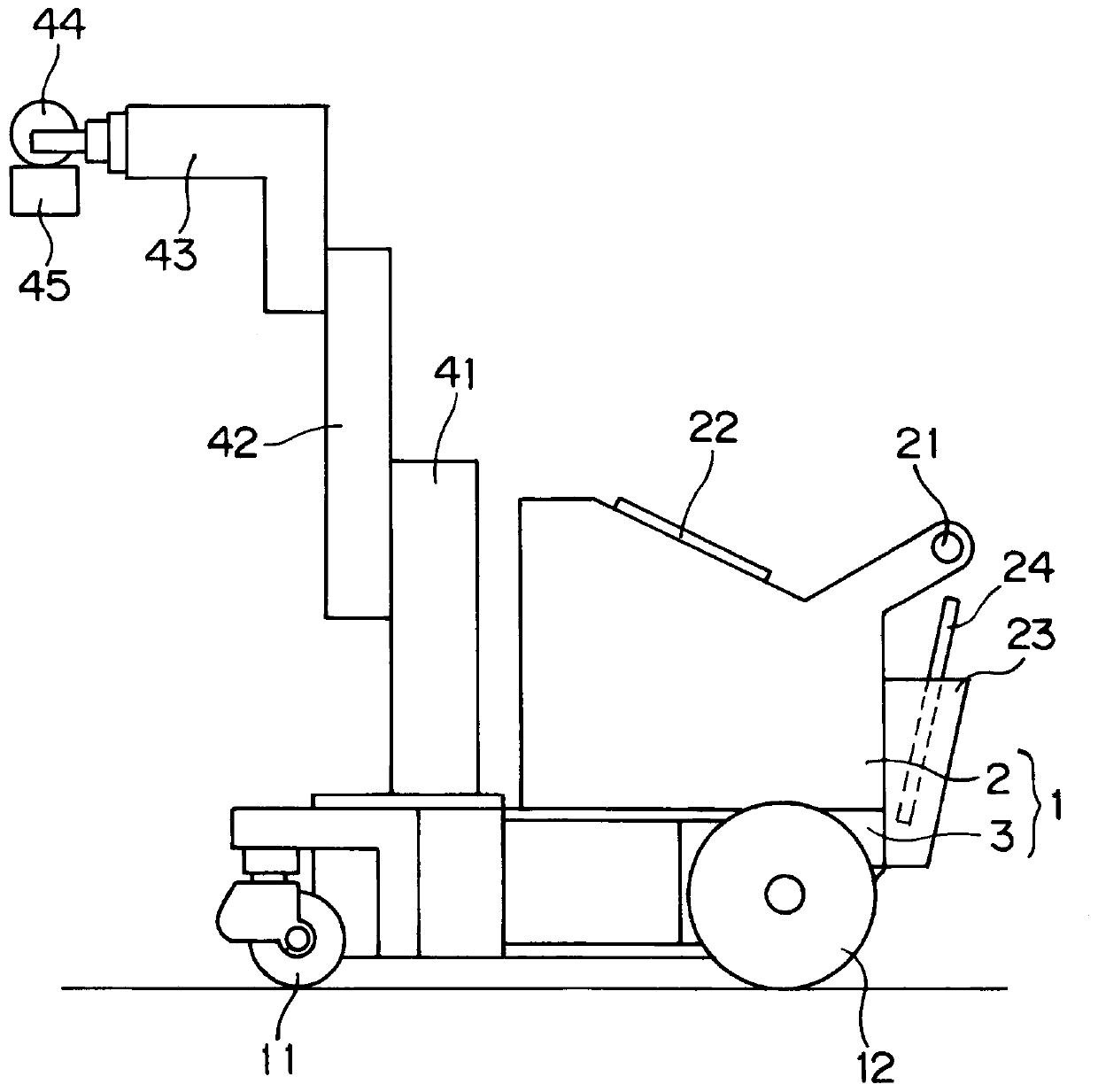
[0033] Embodiments of the present invention will be described below with reference to the drawings. figure 1 It is a schematic diagram of a mobile X-ray radiographic apparatus as a mobile radiographic apparatus of the present invention.

[0034] This mobile X-ray imaging device is also referred to as an X-ray imaging device for outpatient visits, moves between wards to perform X-ray imaging, and has a main body 1 formed of a body 2 and a gantry 3 . A pair of left and right front wheels 11 serving as wheels for changing directions are arranged on the front side in the traveling direction of the gantry 3 of the mobile X-ray imaging apparatus. In addition, a pair of left and right rear wheels 12 serving as driving wheels are disposed on the rear side in the advancing direction of the gantry 3 of the mobile X-ray imaging apparatus.

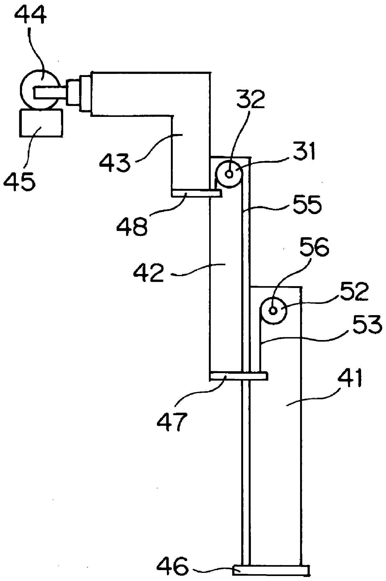
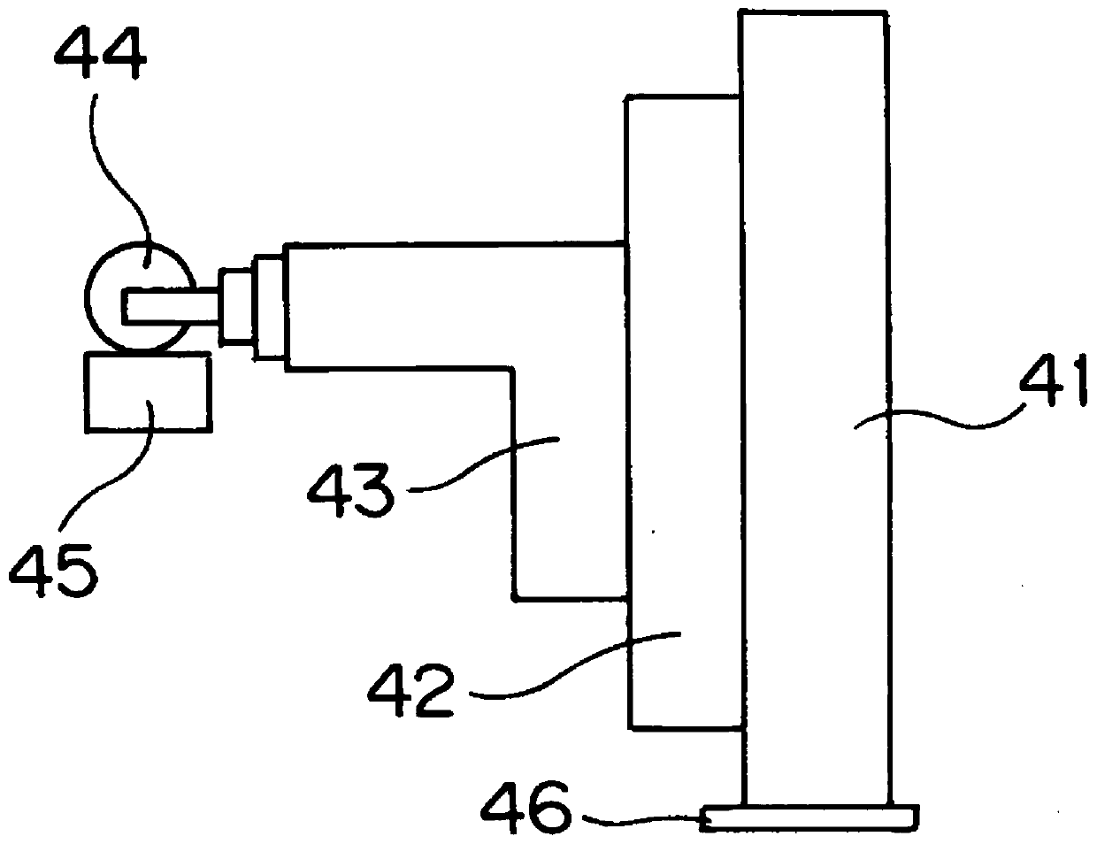
[0035] A pillar 41 is erected on the front side in the traveling direction of the frame 3 constituting the main body 1 , and the first elevating me...


PUM


Abstract

The axial direction B of a spindle 64 that supports moving pulleys 58, 59 is arranged in a position rotated about the axis of a shaft relative to the axial direction of a spindle 56. The axial direction B of the spindle 64 is also arranged inclined at a predetermined angle with respect to the axial direction A when the moving pulleys 58, 59 are in an elevated position. Thus, the moving pulleys 58,59 can be moved automatically to a position at which no stress is applied to a first wire rope 54.

Description

technical field [0001] The present invention relates to a mobile radiographic apparatus. Background technique [0002] A mobile X-ray imaging apparatus which is one type of such a mobile radiographic apparatus is also called an X-ray imaging apparatus for outpatient visits, and is moved between wards to perform X-ray imaging. This mobile X-ray imaging device includes a main body with front wheels and rear wheels, a pillar standing upright from the main body, and a supporting X-ray irradiation part formed by an X-ray tube and a collimator along the An elevating member for elevating the pillar, an X-ray detector for detecting X-rays irradiated from the X-ray irradiation unit and passing through the subject, and a battery arranged inside the main body. [0003] In such a mobile X-ray imaging apparatus, it is necessary to raise and lower the X-ray irradiation unit formed of the X-ray tube and the collimator according to the imaging situation. At this time, since the weight of ...

Claims


Application Information

Patent Timeline
Patent Type & Authority Applications(China)
IPC IPC(8): A61B6/00
CPCA61B6/4405A61B6/4452A61B6/447A61B6/56
Inventor 武本肇早川徹
Owner SHIMADZU SEISAKUSHO CO LTD
Why Eureka
Try Eureka