Supercharge Your Innovation With Domain-Expert AI Agents!

Hydraulic machine mold stamping rod

A technology of hydraulic presses and punching rods, which is applied in the direction of forming tools, manufacturing tools, metal processing equipment, etc., can solve problems such as stress concentration and punching rod breakage, and achieve the effects of uniform force, low pressure, and improved service life

Inactive Publication Date: 2019-10-11
南京点金焊业有限责任公司
View PDF0 Cites 0 Cited by
  • Summary
  • Abstract
  • Description
  • Claims
  • Application Information

AI Technical Summary

Problems solved by technology

[0003] The purpose of the present invention is to provide a hydraulic press die punching rod, which solves the technical problem that the stepped punching rod in the prior art causes stress concentration during the stamping process, and the punching rod is easy to break from the step

Method used


Image

  • Hydraulic machine mold stamping rod
  • Hydraulic machine mold stamping rod
  • Hydraulic machine mold stamping rod

Examples


Embodiment Construction

[0016] In order to make the purpose and technical solution of the present invention clearer, the technical solution of the present invention will be clearly and completely described below in conjunction with the embodiments of the present invention.

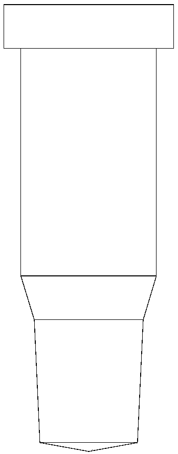
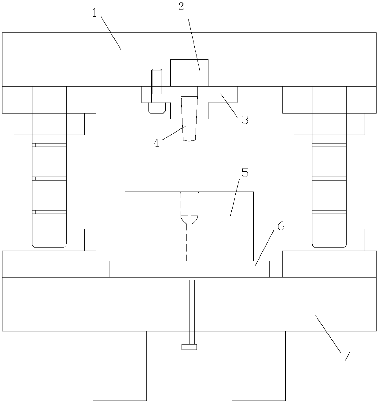
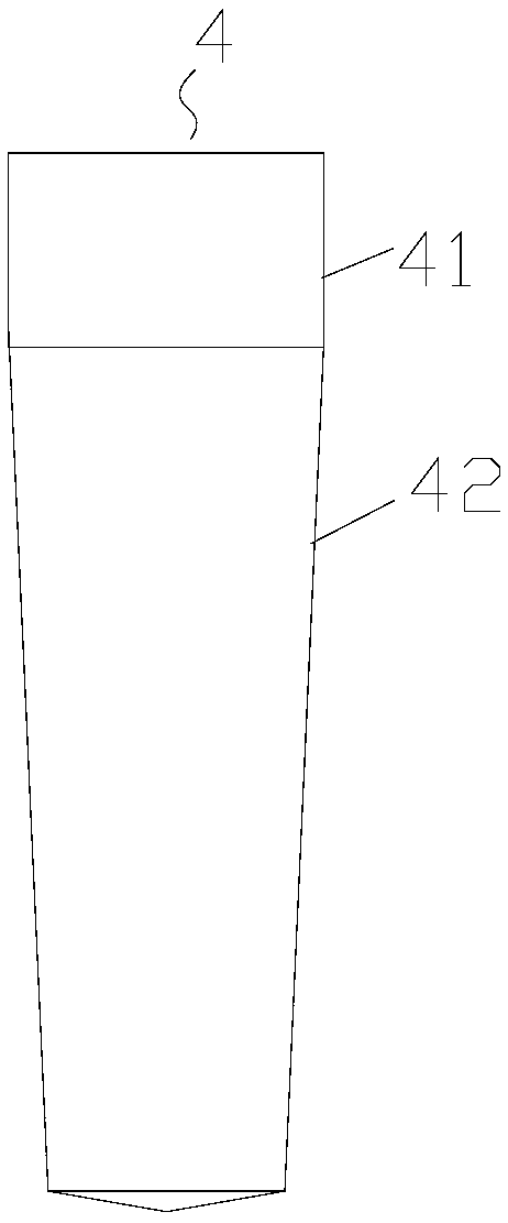
[0017] Such as figure 2 , 3 As shown, a hydraulic press mold for an electrode cap includes an upper mold base 1, an upper backing plate 2, an upper clamping plate 3, a punch 4, a lower template 5, a lower mold pad 6 and a lower mold base 7, and the punch 4 is a rotary The body is divided into two sections along its length, including a cylindrical section 41 and a circular frustum section 42. The two sections are integrally formed, and the junction is smoothly transitioned. The diameter of the end of the circular platform section away from the cylindrical section is small. The ratio is 1:4; the taper of the frustum segment 42 is 1:10. The installation cavity for clamping the punch in the upper clamping plate includes an upper c...


PUM


Abstract

The invention discloses a hydraulic machine mold stamping rod. The hydraulic machine mold stamping rod comprises an upper mold base, an upper cushion plate, an upper clamping plate, a stamping rod body, a lower mold plate, a lower mold cushion and a lower mold base. The stamping rod body is a rotating body and is divided into two segments, namely the cylindrical segment and the circular-truncated-cone segment, in the length direction, and the two segments are integrally formed. The connecting position is in the smooth transition condition. The diameter of the end, away from the cylindrical segment, of the circular-truncated-cone segment is small. A mounting cavity which allows the stamping rod body to be mounted therein and is formed in the upper clamping plate comprises an upper clampingcavity and a lower clamping cavity from top to bottom along the axis. The connecting position of the cylindrical segment and the circular-truncated-cone segment of the stamping rod body is in the smooth transition condition. In the stamping process, the upper portion of the circular-truncated-cone segment is completely attached to the inner wall of the lower camping cavity, and the outer surface of the upper portion of the circular-truncated-cone segment is a force bearing face. The force bearing area is large; the pressure intensity is small; force is borne in a uniform and balanced manner; the stamping rod body is not likely to be fractured; the service life is prolonged; and the machining cost is lowered.

Description

technical field [0001] The invention relates to a die punch rod of a hydraulic press. Background technique [0002] The electrode cap on the spot welding machine is a stamping part. In the prior art, the stamping rod of the hydraulic press mold is in the shape of a ladder, such as figure 1 As shown, in the stamping process, the step surface is the force-bearing surface, which is subjected to upward compressive stress, resulting in stress concentration, and the punch is easy to break from the step. Contents of the invention [0003] The object of the present invention is to provide a hydraulic press die punching rod, which solves the technical problem in the prior art that the stepped punching rod causes stress concentration during the punching process, and the punching rod is easy to break from the step. [0004] In order to achieve the above object, the present invention is achieved through the following technical solutions: [0005] A mold for an electrode cap hydrauli...

Claims


Application Information

Patent Timeline
Patent Type & Authority Applications(China)
IPC IPC(8): B21D37/10
CPCB21D37/10
Inventor 芮新民周荣荣孔国宏
Owner 南京点金焊业有限责任公司
Features
  • R&D
  • Intellectual Property
  • Life Sciences
  • Materials
  • Tech Scout
  • Unparalleled Data Quality
  • Higher Quality Content
  • 60% Fewer Hallucinations
Learn More