
Automatic locking device and method

An automatic locking and locking technology, applied in metal processing, metal processing equipment, manufacturing tools, etc., can solve the problems of installation errors, working errors, affecting the locking and paying accuracy, etc., to reduce installation errors and working errors, and achieve high locking and paying accuracy. Effect

Active Publication Date: 2019-10-11
深圳市宏锦电子有限公司
View PDF7 Cites 4 Cited by
  • Summary
  • Abstract
  • Description
  • Claims
  • Application Information

AI Technical Summary

Problems solved by technology

Although this solution realizes the automatic retrieving and locking of screws, the double-level driving locking structure and locking method will lead to the superposition of installation errors and working errors, thus affecting the accuracy of locking

Method used


Image

  • Automatic locking device and method
  • Automatic locking device and method
  • Automatic locking device and method

Examples


Embodiment Construction

[0032] The technical solutions in the embodiments of the present invention will be clearly and completely described below in conjunction with the accompanying drawings in the embodiments of the present invention. Obviously, the described embodiments are only a part of the embodiments of the present invention, rather than all the embodiments. The components of the embodiments of the present invention generally described and illustrated in the drawings herein may be arranged and designed in various different configurations. Therefore, the following detailed description of the embodiments of the present invention provided in the accompanying drawings is not intended to limit the scope of the claimed invention, but merely represents selected embodiments of the present invention. Based on the embodiments of the present invention, all other embodiments obtained by those skilled in the art without creative work shall fall within the protection scope of the present invention.

[0033] Su...


PUM


Abstract

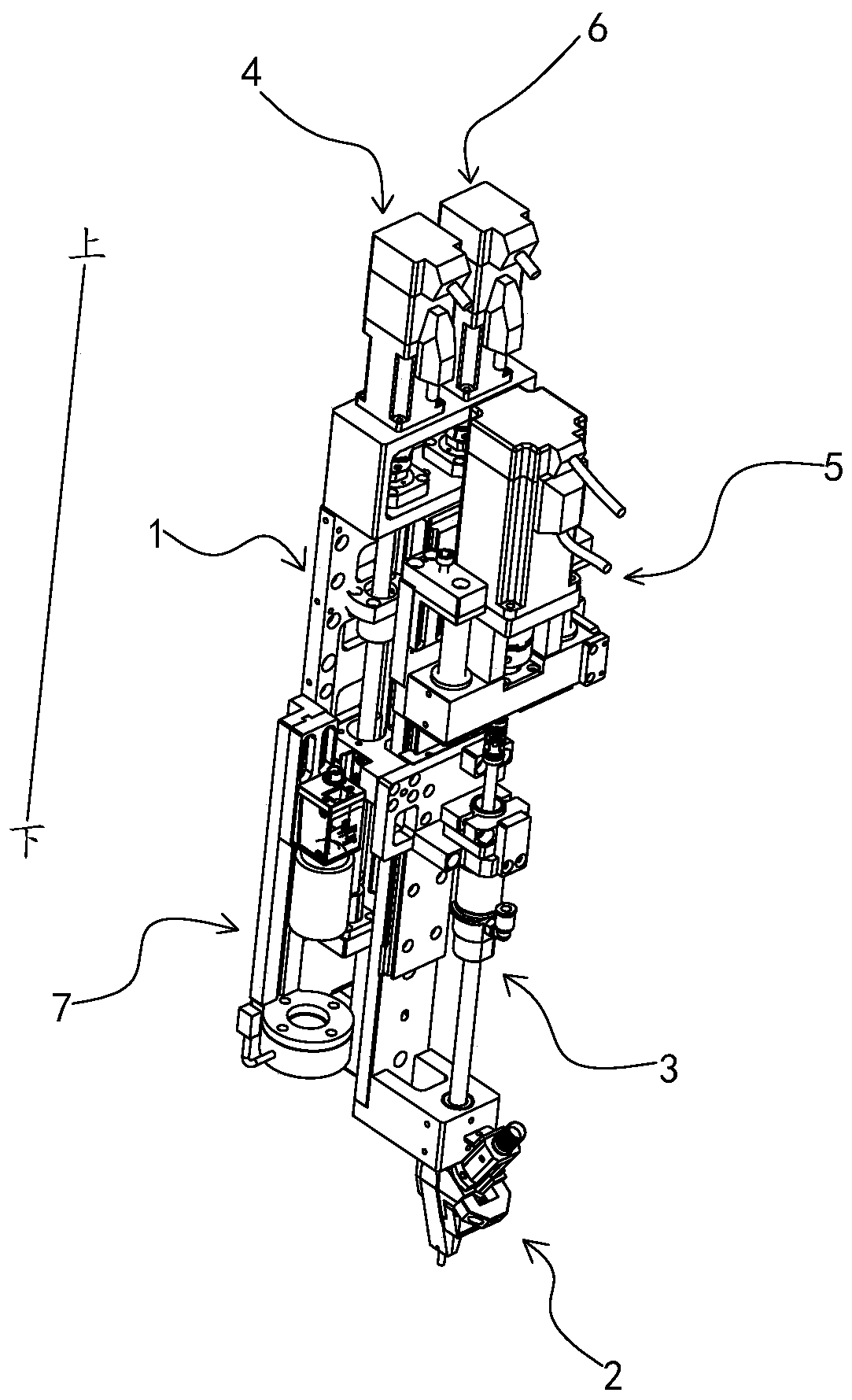
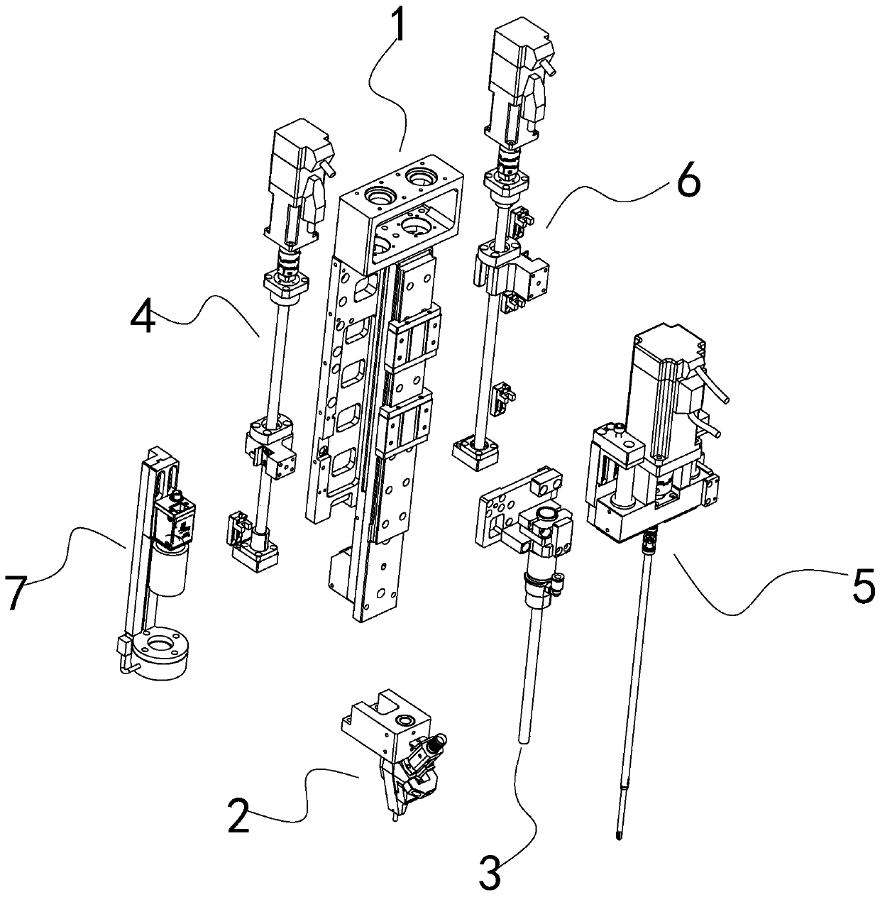
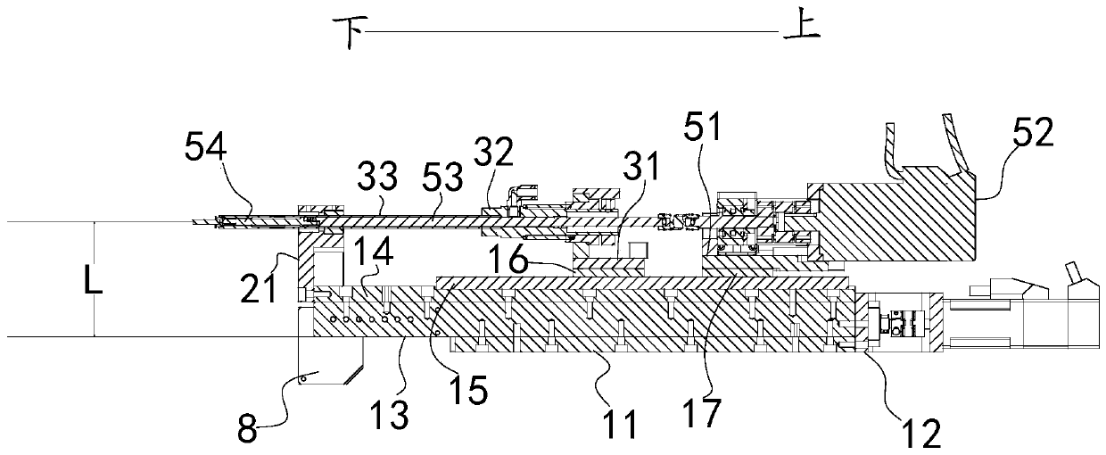
The invention discloses an automatic locking device and method. The automatic locking device comprises a conveying chuck for feeding, a taking assembly for taking materials from the conveying chuck, afirst driving assembly for driving the taking assembly to drive, a locking assembly for carrying out locking and a second driving assembly for driving the locking assembly to move. The taking assembly and the first driving assembly are connected, and the locking assembly and the second driving assembly are connected. The taking assembly is located between the conveying chuck and the second driving assembly. According to the automatic locking device, the first driving assembly and the second driving assembly drive the taking assembly and the locking assembly to lock the product, the mounting error and the work error of the automatic locking device are reduced, and the locking precision is high.

Description

Technical field [0001] The invention relates to the field of automatic locking and payment, in particular to an automatic locking and payment device and an automatic locking and payment method. Background technique [0002] Threaded connection is a widely used detachable fixed connection method. In order to reduce manpower input, more and more manufacturing enterprises use automated machines such as screw machines to replace the traditional manual screw tightening process. [0003] The patent application with the application number 201721888890.X discloses an automatic lock payment module, which is driven by the drive assembly to move the lock payment assembly down to take the material, and then the drive assembly drives the lock payment assembly to continue to move down to reach the lock payment on the product to be locked Position; and then start the electric screwdriver through the locking cylinder to press down to lock the screw into the product. Although this solution realiz...

Claims


Application Information

Patent Timeline
Patent Type & Authority Applications(China)
IPC IPC(8): B23P19/06
CPCB23P19/06
Inventor 刘和平
Owner 深圳市宏锦电子有限公司
Learn More