Optical transmitting/receiving module

A receiving module and optical transmission technology, applied in optics, light guides, lasers, etc., can solve the problems of large installation error, large area of ​​flat substrate, and large space limitation, so as to improve position accuracy, reduce installation errors, reduce The effect of space constraints

Inactive Publication Date: 2007-02-21
HAMAMATSU PHOTONICS KK
View PDF1 Cites 12 Cited by
  • Summary
  • Abstract
  • Description
  • Claims
  • Application Information

AI Technical Summary

Problems solved by technology

Therefore, it is necessary to arrange the receiving photodiode on, for example, the sub-fixer erected on the surface of the planar substrate, so there will be problems of large installation errors and difficult alignment.
[0006] In addition, it is necessary to install the laser diode for transmission, the photodiode for reception, and the dielectric multilayer film filter on the substrate, so the limitation on space becomes large.
Or, in order to use a form without sub-mounts, there are problems such as the need to use side-illuminated photodiodes, etc.
[0007] In particular, due to the use of the transmission and reflection characteristics of the dielectric multilayer film filter, it is impossible to arrange the laser diode for transmission, the photodiode for reception, and the dielectric multilayer film filter on a straight line. The limitation on the dimensional space becomes larger
Therefore, for example, when these are arranged in an array shape, there is a problem that the area of ​​the planar substrate must be set to be very large.

Method used


Image

  • Optical transmitting/receiving module
  • Optical transmitting/receiving module
  • Optical transmitting/receiving module

Examples


Embodiment Construction

[0036] Hereinafter, preferred embodiments of the present invention will be described with reference to the drawings. In addition, in each embodiment, the same figure number is attached|subjected to the part which has the same function, and repeated description is abbreviate|omitted.

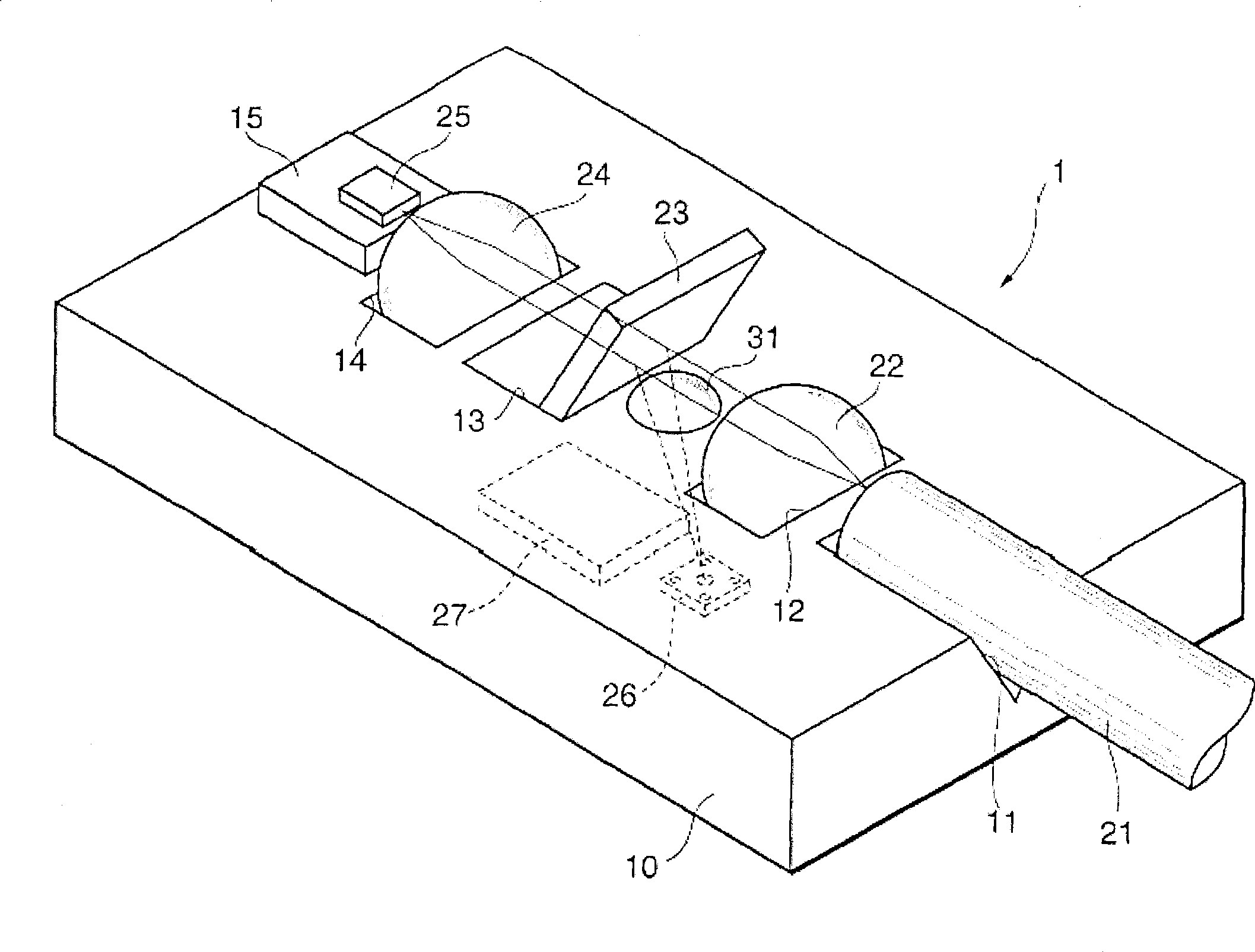
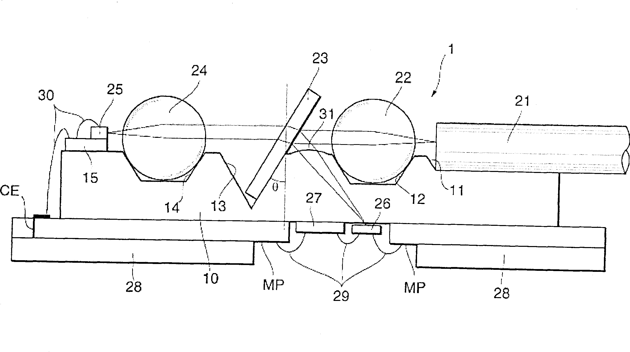
[0037] Fig. 1 is a perspective view of an optical transmission / reception module according to a first embodiment of the present invention, and Fig. 2 is a cross-sectional view thereof.

[0038] As shown in Fig. 1 and Fig. 2, the optical transmission / reception module 1 of the present embodiment is, for example, a module used in households when connecting a household and a base station (base station) with an optical fiber for optical communication. Sexual substrate 10. The light-transmitting substrate 10 is a silicon substrate, and transmits light having a wavelength of 1.55 μm band used in download communication. On the surface of the light-transmitting substrate 10 are formed a V-groove 11, a fi...


PUM


Abstract

An optical transmitting/receiving module in which spatial restriction can be relaxed by eliminating the need for providing a substrate with a submount for a photodiode. A optical transmitting/receiving module (1) comprises a light transmitting substrate (10). A groove (13) for filter is formed in the surface of the light transmitting substrate (10) and a dielectric multilayer film filter (23) is placed in the groove (13) for filter. An optical fiber (21) and a laser diode (25) are arranged oppositely on the opposite sides of the dielectric multilayer film filter (23). Furthermore, a photodiode (26) is provided on the rear side of the light transmitting substrate (10). The photodiode (26) is arranged right under a line connecting the optical fiber (21) and the laser diode (25).

Description

technical field [0001] The invention relates to an optical transmission / reception module for optical transmission / reception, which is used in optical communication or optical information processing and the like. Background technique [0002] When optical transmission / reception is performed by connecting a home and a base station with an optical fiber, for example, an optical transmission / reception module using a wavelength division multiplexing method using optical signals in the uplink 1.3μm band and downlink 1.55μm band has been developed. As such an optical transmission / reception module, for example, there is a module disclosed in Japanese Patent Application Laid-Open No. 11-68705 (Patent Document 1). [0003] The optical transmission / reception module has a planar substrate on which an optical branch waveguide is formed. A groove is provided at the branching portion of the optical branching waveguide, and a dielectric multilayer film filter is placed in the groove to bra...

Claims


Application Information

Patent Timeline
Patent Type & Authority Applications(China)
IPC IPC(8): G02B6/42G02B6/12H01L31/12H01S5/022H01S5/026
CPCG02B6/4246
Inventor 藁科祯久星野安司竹山创武藤雅昭
Owner HAMAMATSU PHOTONICS KK
Why Eureka
Try Eureka