Contact-type electric capacitive displacement sensor

a capacitive displacement sensor and contact-type technology, applied in the direction of electric/magnetic measuring arrangements, instruments, force measurement, etc., can solve the problems of extreme care for the installation of the displacement sensor, limited displacement measurement range, and reduced reliability of measurement, so as to reduce the mechanical installation error

Inactive Publication Date: 2008-03-25
MOON WONKYU
View PDF7 Cites 11 Cited by
  • Summary
  • Abstract
  • Description
  • Claims
  • Application Information

AI Technical Summary

Benefits of technology

[0007]It is, therefore, a primary object of the present invention to provide a contact-type electric capacitive displacement sensor employing an area variation measurement method, capable of reducing a mechanical installation error and an error that might be caused by a discrepancy between a driving direction and a measurement direction.
[0008]It is another object of the present invention to provide a contact-type electric capacitive displacement sensor employing an area variation measurement method, capable of measuring a displacement in a wide range and saving an installation space by way of making a driving direction and a measurement direction coincident with each other.

Problems solved by technology

However, this method has a disadvantage in that it has a very limited measurement range for displacement since its sensitivity rapidly decreases nonlinearly as the displacement increases.
Further, the gap (space) variation measurement method is very sensitive to a mechanical installation error, so extreme care must be taken for the installation of the displacement sensor.
In particular, in this method, the reliability of measurement may be greatly reduced due to an abbe error, a cosine error and the like that can be caused by a discrepancy between a driving direction (e.g., a horizontal direction) and a measurement direction (e.g., a vertical direction).
Also, the method is also disadvantageous with regard to effective space utilization.
Specifically, a condition for velocity has been eased considerably, and also a mechanical installation error rather than an electric noise has risen as an important issue to be solved.

Method used


Image

  • Contact-type electric capacitive displacement sensor
  • Contact-type electric capacitive displacement sensor
  • Contact-type electric capacitive displacement sensor

Examples


Embodiment Construction

[0017]Hereinafter, preferred embodiments of the present invention will be described in detail with reference to the accompanying drawings. In the drawings, the same or similar elements are denoted by the same reference numerals even though they are depicted in different drawings.

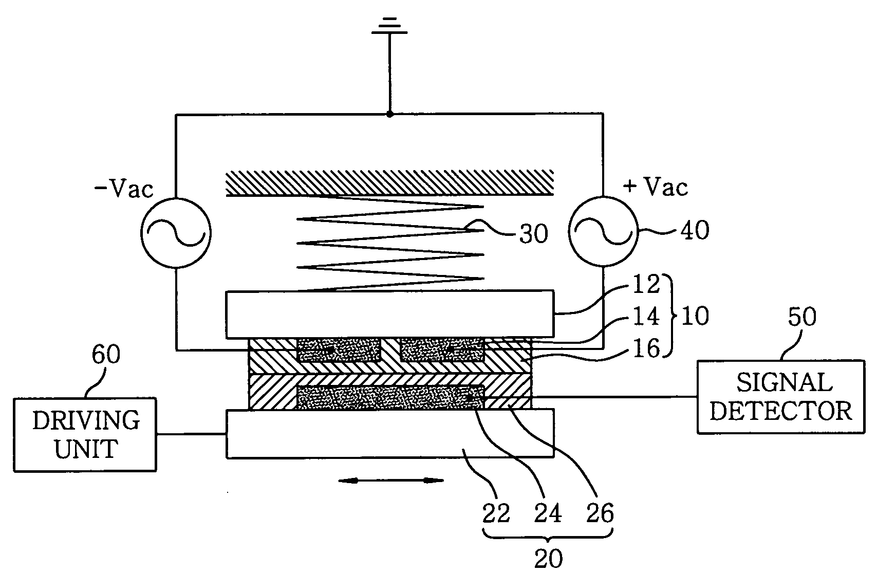
[0018]FIG. 1 is a schematic view of a contact-type electric capacitive displacement sensor in accordance with a first preferred embodiment of the present invention.

[0019]As shown in FIG. 1, the contact-type electric capacitive displacement sensor includes a stationary element 10 and a displaceable element 20. The stationary element 10 has a stationary plate 12, a stationary conductive pattern (or a stationary electrode pattern) 14 formed on the stationary plate 12, and a stationary insulation film 16 uniformly coated over the stationary plate 12 to cover the conductive pattern 14. Likewise, the displaceable element 20 has a displaceable plate 22, a displaceable conductive pattern (or a displaceable electrode...


PUM

PropertyMeasurementUnit
dielectric constantaaaaaaaaaa
conductiveaaaaaaaaaa

Abstract

A contact-type electric capacitive displacement sensor includes a stationary element having a stationary plate, a stationary conductive pattern formed on the stationary plate and an insulation film coated on the stationary plate and a displaceable element having a displaceable plate, a displaceable conductive pattern formed on the displaceable plate and an insulation film coated on the displaceable plate. The stationary and the displaceable conductive patterns have a cyclic pattern of conductor to thereby produce a variation of capacitance therebetween when moving relative to each other.

Description

FIELD OF THE INVENTION[0001]The present invention relates to a contact-type electric capacitive displacement sensor for measuring a minute linear displacement; and, more particularly, to a contact-type electric capacitive displacement sensor employing an area variation measurement mechanism for detecting a displacement by way of measuring a variation in capacitance corresponding to a variation in an overlapped area of conductive patterns of a stationary element and a displaceable element when they are moved relative to each other in parallel.BACKGROUND OF THE INVENTION[0002]In general, an electric capacitive displacement sensor is a device for producing an electric signal indicating a variation in capacitance corresponding to a displacement between two conductive plates. When the two conductive plates are disposed to face with each other in parallel, the capacitance therebetween is proportional to a dielectric constant of a medium interposed between the two plates and the areas of t...

Claims


Application Information

Patent Timeline
Patent Type & Authority Patents(United States)
IPC IPC(8): G01B7/16G01L1/00
CPCG01D5/00G01D5/2412
Inventor MOON, WONKYUKIM, MOOJIN
Owner MOON WONKYU
Why Eureka
Try Eureka