[0030] The technical solutions of the present invention will be clearly and completely described below in conjunction with embodiments. Obviously, the described embodiments are only a part of the embodiments of the present invention, rather than all the embodiments. Based on the embodiments of the present invention, all other embodiments obtained by those of ordinary skill in the art without creative work shall fall within the protection scope of the present invention.
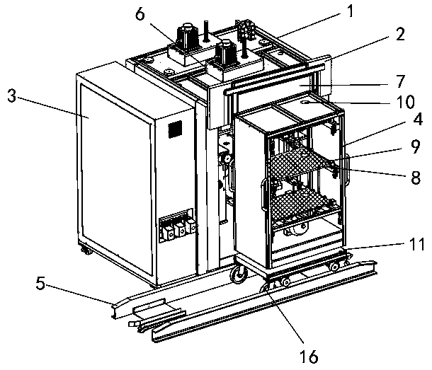
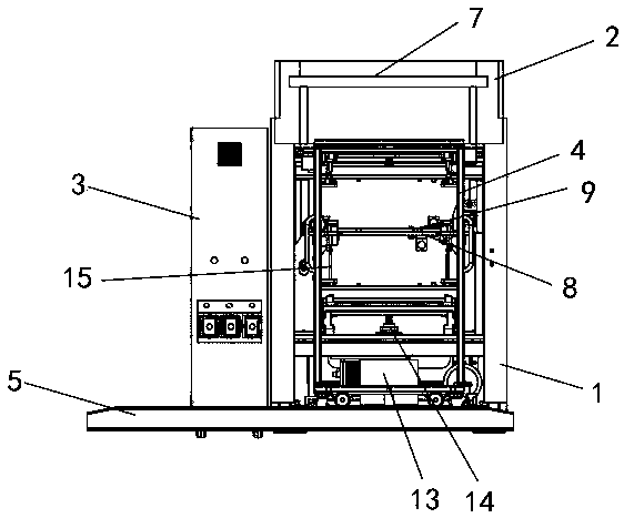
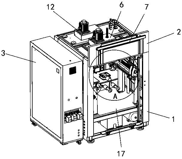
[0031] See Figure 1-7 As shown, a constant temperature heating device for the production of fine art painting pen brushes includes a constant temperature heating box 1, a recovery box 3, a heating rack 4, and a sliding rack 5. The recovery box 3 is located on the side of the constant temperature heating box 1, and the heating rack 4 is located at the constant temperature. One side of the heating box 1, and the heating rack 4 is movably connected to the heating area 17 inside the constant temperature heating box 1. A power supply 12 is installed on the top of the constant temperature heating box 1, a hydraulic drive 6 is installed on the side of the power supply 12, and the top side wall of the constant temperature heating box 1 A fixed groove 18 is provided. A gate seat 2 is fixedly installed on the fixed groove 18, a movable gate 7 is installed on the gate seat 2, and the gate 7 is connected with a hydraulic drive 6, and a built-in hydraulic pump 19 is installed inside the heating area 17 with built-in Two built-in hydraulic telescopic rods 20 are connected to the side wall of the hydraulic pump 19, and the same end of the two built-in hydraulic telescopic rods 20 are connected to a suction cup 21. Both suction cups 21 are connected to the outer wall of the heating frame 4, and the top of the built-in hydraulic pump 19 A suction fan 22 is installed. The suction fan 22 is connected to two suction cups 21 through two ducts 23 respectively. A side frame 24 is fixed on the inner wall of one side of the heating area 17 and a suction pump 25 is installed on the side frame 24. An air pump 26 is installed on the side wall of 25, and an air pump 29 is installed at the bottom of the air pump 26. The bottom of the air pump 29 is connected to a pneumatic telescopic suction tube 27. Two evenly distributed suction holes 28 are provided on the side wall of the pneumatic telescopic suction tube 27. The air pump 25 is connected to the recovery box 3 through an air pipe 30, and the suction pump 25 is connected to the pneumatic telescopic suction pipe 27 through another air pipe 30, and the air pump 26 is connected to the recovery box 3 through an air pipe 30, and The suction pump 26 is connected to the pneumatic telescopic suction pipe 27 through another air pipe 30;
[0032] A sliding plate 11 is installed at the bottom of the heating rack 4, a number of pulleys 16 are installed between the sliding plate 11 and the heating rack 4, and a number of pulleys 16 are installed at the bottom of the sliding plate 11, the sliding plate 11 is installed on the sliding rack 5, and the heating rack 4 is installed inside There are two evenly spaced placement racks 8, which are connected by two support rods 15 between them. A grid splint 9 is installed above the two placement racks 8, and the bottom of the placement rack 8 is connected at the bottom. There is a bottom hydraulic telescopic rod 14, the bottom end of the bottom hydraulic telescopic rod 14 is connected with the bottom hydraulic pump 13, the top of the heating rack 4 and the same position on the two placing racks 8 are provided with a butting hole 10.
[0033] The heating frame 4 is movably connected to the inner wall of the constant temperature heating box 1 through two built-in hydraulic telescopic rods 20, and the heating frame 4 is movably connected to the sliding frame 5 through the sliding plate 11.
[0034] The two placing racks 8 are movably connected with the inner wall of the heating rack 4 through the bottom hydraulic telescopic rod 14, and the two placing racks 8 move synchronously through the support rod 15.
[0035] The docking hole 10 matches the diameter of the pneumatic telescopic suction tube 27, and the position of the docking hole 10 after the heating frame 4 is put into the constant temperature heating box 1 corresponds to the pneumatic telescopic suction tube 27.
[0036] The placing frame 8 and the grid splint 9 are both grid-like structures with meshes.
[0037] The pneumatic telescopic suction pipe 27 is movably connected to the inner wall of the heating frame 4 through the air pump 29, and after the pneumatic telescopic suction pipe 27 is fully extended, the two suction holes 28 are exposed and are respectively located below the two placing frames 8.
[0038] The gate 7 is movably connected to the outer wall of the constant temperature heating box 1 through a hydraulic drive 6, and the area of the gate 7 is adapted to the opening size of the constant temperature heating box 1.
[0039] A method of using a constant temperature heating device for producing fine art painting pens, the specific steps are:
[0040] Step 1: Before use, move the heating frame 4 to the opening position of the constant temperature heating box 1 through the sliding plate 11, remove the grid splint 9 on the placing frame 8, and then place the brush bristles to be heated on the placing frame 8. Then use the grid splint 9 to fix, then start the built-in hydraulic pump 19 and the suction fan 22, use the built-in hydraulic pump 19 to drive the built-in hydraulic telescopic rod 20 to contract, and use the suction fan 22 to drive the suction cup 21 to adsorb the heating frame 4, thereby heating The rack 4 is housed inside the constant temperature heating box 1;
[0041] Step 2: After the thermostatic heating box 1 is completely put into the thermostatic heating box 1, the hydraulic drive 6 is used to drive the gate 7 to close the opening of the thermostatic heating box 1, thereby closing the thermostatic heating box 1, and then start the thermostatic heating box 1 and the bottom The hydraulic pump 13 uses the bottom hydraulic pump 13 to drive the bottom hydraulic telescopic rod 14 to expand and contract. With the cooperation of the support rod 15, the two placing frames 8 move up and down inside the constant temperature heating box 1;
[0042] Step 3: Finally, the heating of the brush hair is completed. When the brush hair needs to be taken out, the air pump 29 is started first, and the air pump 29 is used to drive the pneumatic telescopic suction tube 27 to extend, and the two suction holes 28 are respectively connected under the two placing frames 8 At this time, restart the suction pump 25, use the suction pump 25 to draw the high-temperature air flow inside the heating rack 4 into the recovery box 3, and then drive the air pump 29 to reset the pneumatic telescopic suction pipe 27. At this time, open the gate 7 and use the built-in hydraulic pressure The pump 19 pushes the heating frame 4 from the inside of the constant temperature heating box 1 back onto the sliding plate 11. The staff pushes the sliding plate 11 to move the heating frame 4 to the end of the sliding frame 5, and then the brush bristles that have been heated can be taken out. After placing the next batch of brush bristles to be heated on the rack 4, put the heating rack 4 into the constant temperature heating box 1 in the above step 1, close the gate 7, drive the air pump 29 to extend the pneumatic telescopic suction tube 27, and use the suction The air pump 26 reintroduces the high-temperature air stream stored in the recovery box 3 into the heating frame 4, and at this time, the constant temperature heating box 1 is restarted.
[0043] The beneficial effects of the present invention are: due to the presence of the bottom hydraulic pump 13, the bottom hydraulic telescopic rod 14 and the support rod 15 located between the two placement frames 8, the constant temperature heating box 1 can use The bottom hydraulic pump 13 drives the bottom hydraulic telescopic rod 14 to expand and contract. With the support of the support rod 15, the two placing racks 8 move up and down inside the constant temperature heating box 1, and the two placing racks 8 keep moving synchronously while moving up and down. 8 enables the airflow inside the constant temperature heating box 1 to keep flowing under the movement of the placing rack 8, so that the internal temperature of the constant temperature heating box 1 can be kept uniform. Compared with the traditional constant temperature heating device, it can effectively reduce the uneven temperature inside the cabinet. The result is poor hot discharging effect.
[0044] Due to the existence of the grid splint 9, it can fix the position of the brush bristles to prevent them from falling off, and since the grid splint 9 and the placement frame 8 are both grid-like structures with meshes, the brush bristles are heated during the heating process. Speed up heating and enhance the heating effect through exercise.
[0045] Due to the existence of the pneumatic telescopic suction pipe 27 connected to the suction pump 25, the suction pump 26, the suction pump 25, and the suction pump 26, the high-temperature air flow inside the heating area of the constant temperature heating box 1 can first pass through the start-up air pump 29, using the air pump 29 The pneumatic telescopic suction pipe 27 is driven to extend, so that the two suction holes 28 are respectively connected under the two placing racks 8. At this time, the suction pump 25 is started first, and the suction pump 25 is used to draw the high-temperature airflow inside the heating rack 4 Enter the recovery box 3, and then drive the air pump 29 to reset the pneumatic telescopic suction tube 27. At this time, open the gate 7, and use the built-in hydraulic pump 19 to push the heating rack 4 out of the constant temperature heating box 1 back to the slide 11, and the staff pushes the slide 11 to Move the heating frame 4 to the end of the sliding frame 5 to take out the brush bristles that have been heated. When the next batch of brush bristles that need to be heated is placed on the heating frame 4, put the heating frame 4 in the way described above Inside the thermostatic heating box 1, close the gate 7, drive the air pump 29 to extend the pneumatic telescopic suction tube 27, and use the air pump 26 to re-introduct the high-temperature air stored in the recovery box 3 into the heating frame 4. At this time, the thermostatic heating box 1 only needs to It consumes less power to maintain the temperature required to heat the brush bristles, which is more energy-saving, and the heating frame 4 has been drawn off the high-temperature air flow before being taken out, so the brush bristles on it can cool down more quickly, shortening the staff waiting to cool down Time, effectively improve work efficiency.
[0046] When the present invention is in use, firstly, the entire device is assembled, the sliding plate 11 is installed at the bottom of the heating frame 4, and the sliding plate 11 is installed on the sliding frame 5, and then inside the constant temperature heating box 1 (model: DHG-9148A) Install the built-in hydraulic pump 19, and install the suction fan 22 on the top of the built-in hydraulic pump 19. The suction fan 22 is connected to the suction cup 21 at the end of the built-in hydraulic telescopic rod 20, and then a side frame is fixedly installed on the inner wall of the thermostatic heating box 1 24. A suction pump 25 is fixedly installed on the side frame 24, and a suction pump 26 is installed on one side of the suction pump 25. The suction pump 25 and the suction pump 26 are connected to the pneumatic telescopic suction pipe 27 through an air pipe 30, and the suction The pump 25 and the suction pump 26 are connected to the recovery box 3 through another air pipe 30, and the two suction cups 21 are connected to the side wall of the heating frame 4, and the device can be put into use after the assembly is completed. Before use, the heating frame 4 is moved to the opening position of the constant temperature heating box 1 through the sliding plate 11, and the grid splint 9 on the placing frame 8 is removed. Then, the brush hairs that need to be heated are placed on the placing frame 8, and then Use the grid splint 9 to fix, then start the built-in hydraulic pump 19 and the suction fan 22, use the built-in hydraulic pump 19 to drive the built-in hydraulic telescopic rod 20 to contract, and use the suction fan 22 to drive the suction cup 21 to adsorb the heating rack 4, thereby storing the heating rack 4 Inside the constant temperature heating box 1, after the constant temperature heating box 1 is completely inside the constant temperature heating box 1, the hydraulic drive 6 is used to drive the gate 7 to close the opening of the constant temperature heating box 1, thereby closing the constant temperature heating box 1, and then start the constant temperature heating box 1 and the bottom hydraulic pump 13. Due to the presence of the bottom hydraulic pump 13, the bottom hydraulic telescopic rod 14 and the support rod 15 located between the two placement frames 8, the constant temperature heating box 1 can be used when heating the brush hair The bottom hydraulic pump 13 drives the bottom hydraulic telescopic rod 14 to expand and contract. With the support of the support rod 15, the two placement frames 8 move up and down inside the constant temperature heating box 1, and the two placement frames 8 keep moving synchronously. Existence, can play a role in fixing the position of the brush bristles to prevent them from falling off, and because the grid splint 9 and the placement frame 8 are both grid-like structures with meshes, so that the brush bristles move faster during the heating process Heat and enhance the heating effect. At the same time, the up and down rack 8 allows the airflow in the thermostatic heating box 1 to keep flowing under the movement of the rack 8, so that the internal temperature of the thermostatic heating box 1 can be kept uniform, which is similar to the traditional thermostatic heating device. In comparison, it can effectively reduce the poor hot discharge effect caused by the uneven temperature inside the chassis. Finally, when the brush hairs are heated and the brush hairs need to be removed, due to the existence of the pneumatic telescopic suction pipe 27 connected to the suction pump 25, the suction pump 26, the suction pump 25, and the suction pump 26, the constant temperature heating box 1 The high-temperature air flow inside the heating area can first pass through the start of the air pump 29, and the air pump 29 is used to drive the pneumatic telescopic suction tube 27 to extend, so that the two suction holes 28 are respectively connected under the two placing racks 8. At this time, the suction pump is started first 25. Use the suction pump 25 to draw the high-temperature air flow inside the heating rack 4 into the recovery box 3, and then drive the air pump 29 to reset the pneumatic telescopic suction pipe 27. At this time, open the gate 7 and use the built-in hydraulic pump 19 to heat the heating rack 4 from a constant temperature The inside of the box 1 is pushed back to the sliding plate 11, the staff pushes the sliding plate 11 to move the heating frame 4 to the end of the sliding frame 5, and then the brush bristles that have been heated can be taken out. When the heating frame 4 is completed, the next batch needs to be heated. After the brush hairs are processed, the heating frame 4 is put into the constant temperature heating box 1 according to the above method, the gate 7 is closed, the air pump 29 is driven to extend the pneumatic telescopic suction tube 27, and the air pump 26 is used to recover the high temperature airflow stored in the box 3 Re-introduction into the heating frame 4, at this time, the constant temperature heating box 1 only needs to consume less power to maintain the temperature required to heat the brush hair, which is more energy-saving.
[0047] The preferred embodiments of the present invention disclosed above are only used to help explain the present invention. The preferred embodiment does not describe all the details in detail, nor does it limit the invention to only specific implementations. Obviously, many modifications and changes can be made according to the content of this manual. This specification selects and specifically describes these embodiments in order to better explain the principles and practical applications of the present invention, so that those skilled in the art can understand and use the present invention well. The present invention is only limited by the claims and their full scope and equivalents.