Hot blade type electronic garbage pyrolysis device

A kind of electronic waste and blade-type technology, which is applied in the direction of special dry distillation, direct heating dry distillation, petroleum industry, etc., can solve the problems of unresolved heat dissipation loss and fixed position heating, inaccurate temperature measurement, and reduce equipment efficiency, so as to increase heat Utilization, increased continuity, and reduced manufacturing costs

Pending Publication Date: 2017-02-22
SHENWU TECH GRP CO LTD
View PDF1 Cites 3 Cited by
  • Summary
  • Abstract
  • Description
  • Claims
  • Application Information

AI Technical Summary

Problems solved by technology

Due to the use of external heating to heat the material, it is difficult to control the temperature, the temperature measurement is not accurate enough, the heat is concentrated on the tube wall, and the heat is transferred to the material through the tube wall, the heat transfer efficiency is low, and tar is easily bonded, which makes the device efficiency low
For example, the patent literature with the publication number CN101020833A discloses a biomass electromagnetic induction pyrolysis liquefaction reactor, which is characterized in that: it includes a screw feeder set on the support frame, the screw feeder is composed of a shell, An inductance coil is wound on the top; the inductance coil is at least one laye

Method used


Image

  • Hot blade type electronic garbage pyrolysis device
  • Hot blade type electronic garbage pyrolysis device
  • Hot blade type electronic garbage pyrolysis device

Examples


Embodiment 1

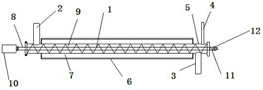
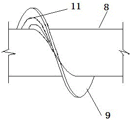
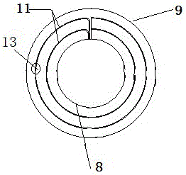
[0034] Example 1: The electric heating system is heated by an electric heating wire with a diameter of 1.4mm and a total length of 15m, which is wound on a spiral blade, and electronic waste materials (mainly circuit boards, wires or keyboards) are made into 3- 6mm particles, the amount of imported material is 1kg / h, the final pyrolysis slag is 0.8kg / h, and the pyrolysis oil gas produced is 0.286 Nm3 / h, which realizes continuous material in and out. During the pyrolysis process, the temperature is continuously maintained At 650°C, the heat source has good stability.

[0035] The oil and gas assay components are as follows:

[0036] Table 1 Composition of e-waste pyrolysis gas

[0037] name H 2

Embodiment 2

[0038] Example 2: The electric heating system is heated by electric heating wires. The diameter of the electric heating wire is 1.4mm and the total length is 10m. The obtained pyrolysis slag is 0.8kg / h, and the pyrolysis oil gas produced is 0.286 Nm3 / h, which realizes continuous material in and out. During the pyrolysis process, the temperature was kept at 650°C, and the heat source was very stable. There are 4 heating wire circuits, and the temperature fluctuation fluctuates at ±20°C.

[0039] The oil and gas assay components are as follows:

[0040] Table 1 Composition of e-waste pyrolysis gas

[0041] name H 2


PUM


Abstract

The invention relates to the technical field of garbage treatment, in particular to a hot blade type electronic garbage pyrolysis device. The hot blade type electronic garbage pyrolysis device comprises an electronic garbage pyrolysis reactor and an electric heating system, wherein the electronic garbage pyrolysis reactor comprises a material pyrolysis assembly and a reactor shell; the material pyrolysis assembly comprises a spiral casing pipe and a propelling helix; the electric heating system comprises an electric heating wire and a power supply rotating joint; and the two ends of the electric heating wire stretch out along a spiral shaft of the propelling helix to be connected with the power supply rotating joint. The device adopts a spiral blade to heat, the electric heating wire is arranged in the propelling spiral shaft blade, materials perform heat transfer from inside to outside while being propelled by the helix, and the materials are directly heated by the high-temperature blade in the propelling process, so the thickness of a heat-preserving layer is reduced, the utilization rate of heat is increased and the production and manufacturing cost is reduced; meanwhile, the heating spiral blade rotates along with the spiral shaft, so the temperature is more uniform.

Description

technical field [0001] The invention relates to the technical field of waste treatment, in particular to a thermal blade type electronic waste pyrolysis device. Background technique [0002] Due to the continuous change of temperature in the pyrolysis process of electronic waste, the products produced by pyrolysis of materials at different temperatures are different. Through experiments and data collation of related materials, it is found that the temperature is between 300~400℃, and the pyrolysis gas The production speed is accelerated, and at the same time, tar is produced at a temperature between 500 and 550 ° C. Due to the increase in temperature, the tar evaporates rapidly into a gaseous oil-gas mixture after production, and the residual solid is carbonized at a temperature between 650 and 700 ° C to form a solid residue. Because the material is heated by external heating, it is difficult to control the temperature, the temperature measurement is not accurate enough, th...

Claims


Application Information

Patent Timeline
IPC IPC(8): C10B53/00C10B49/16
CPCC10B53/00C10B49/16
Inventor 石为华宋敏洁王志军陈珊郭科宏吴道洪
Owner SHENWU TECH GRP CO LTD
Why Eureka
Try Eureka