

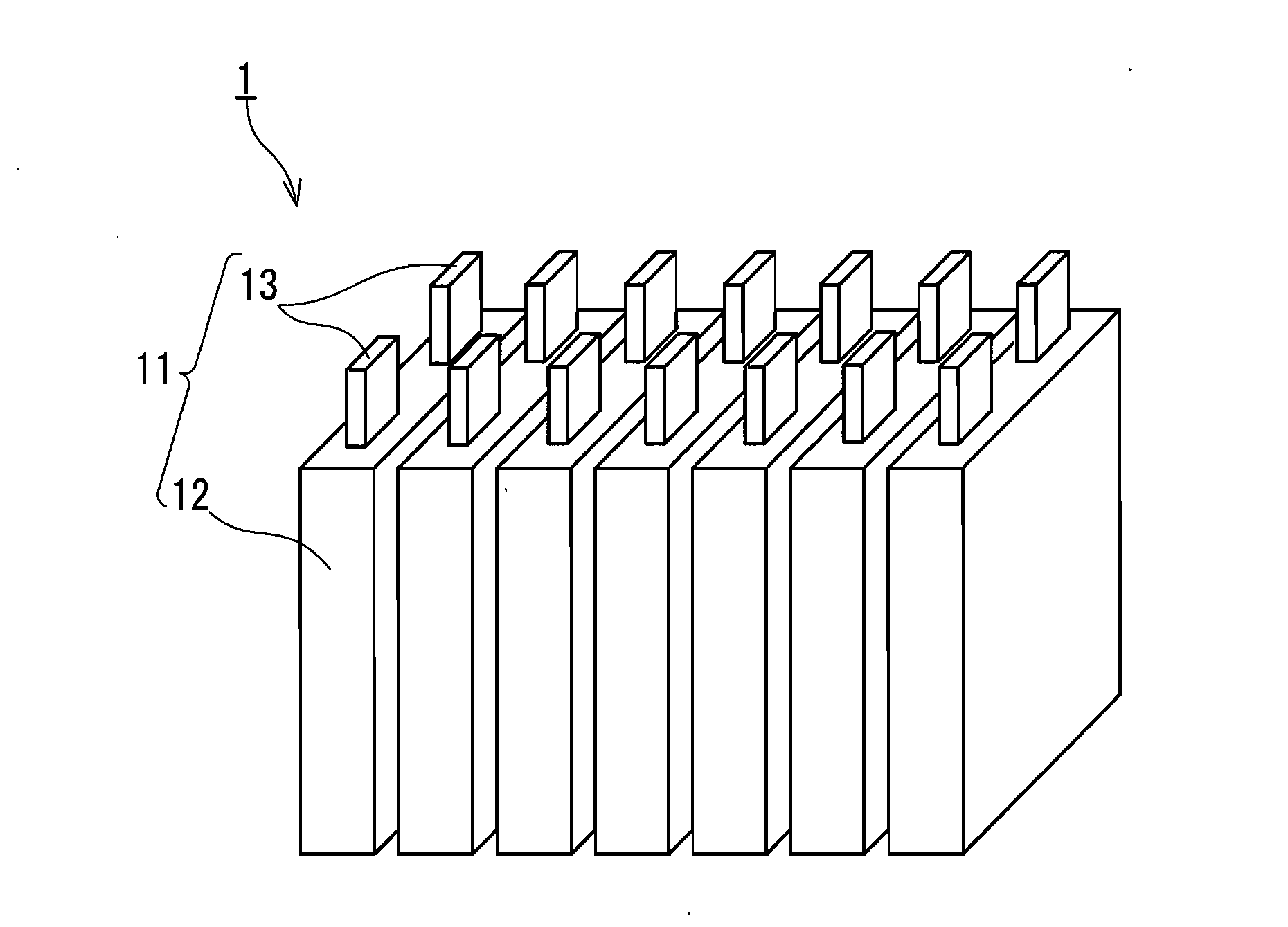
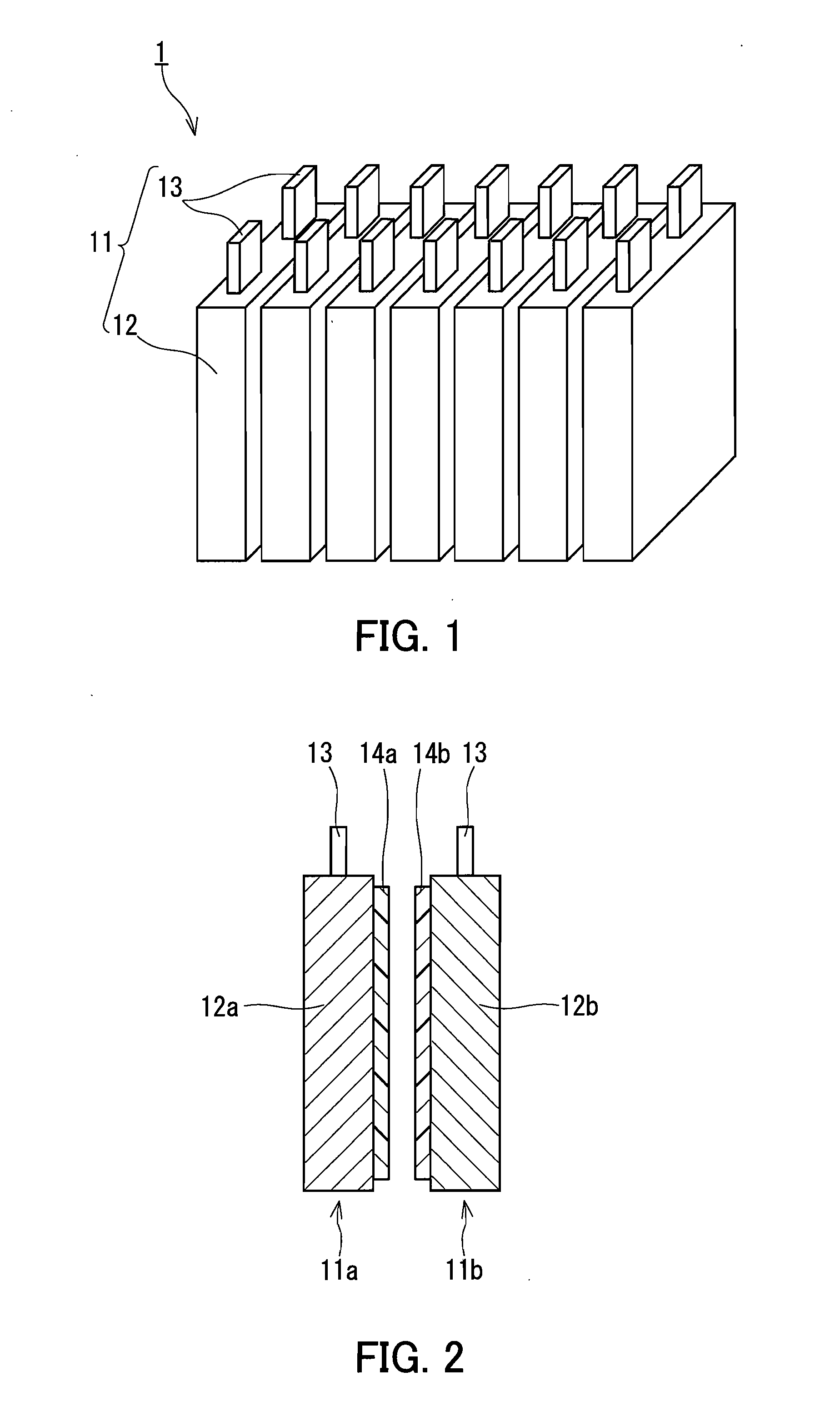
Assembled battery device
a battery device and battery body technology, applied in the direction of batteries, cell components, jackets/cases materials, etc., can solve the problems of reducing the efficiency adversely affecting the output characteristics and lifetime of assembled battery devices, etc., to achieve high thermal emission properties, heat is received efficiently, and the effect of high efficiency
- Summary
- Abstract
- Description
- Claims
- Application Information
AI Technical Summary
Benefits of technology
Problems solved by technology
Method used
Image

Examples
example 1
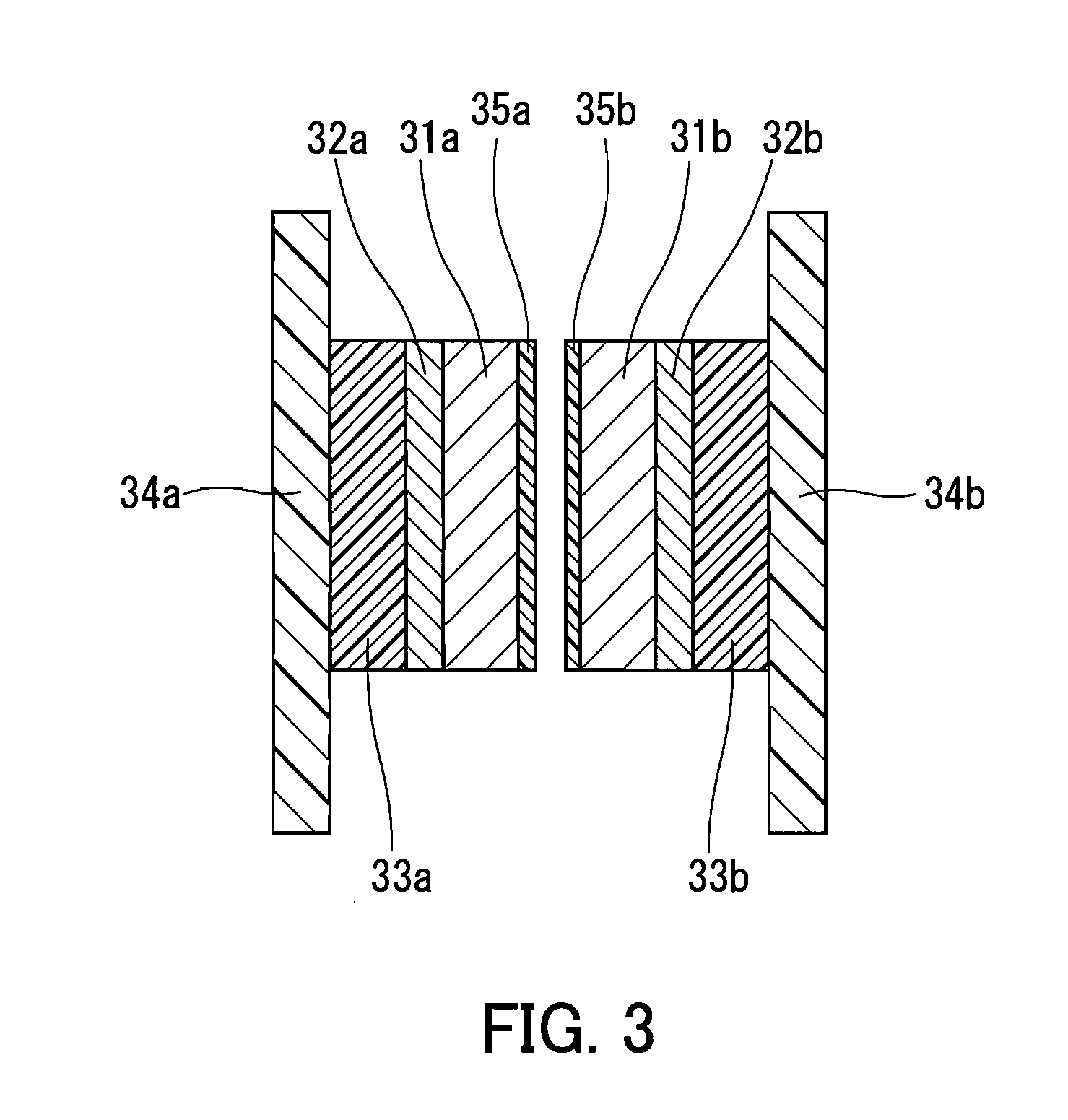
[0027]An evaluation apparatus as shown in FIG. 3 was fabricated, and the thermally-homogenizing effect of thermal emission tapes on single cells was evaluated. A sample was prepared which included an aluminum plate 31a (100 mm long×100 mm wide×15 mm thick), a heater 32a of 4 mm thickness, and a heat insulator 33a of 10 mm thickness that were layered in this order. Furthermore, another sample was prepared which included an aluminum plate 31b (100 mm long×100 mm wide×15 mm thick), a heater 32b of 4 mm thickness, and a heat insulator 33b of 10 mm thickness that were layered in this order. These two samples were held by supporting members 34a and 34b, respectively, in such a manner that the aluminum plate 31a and the aluminum plate 31b faced each other across a gap of 1 mm. Two pieces of NITOFLON (registered trademark) No. 903SC (manufactured by NITTO DENKO CORPORATION, having a thickness of 0.11 mm, and having a total emissivity of 0.95 at a wavelength of 2 μm to 14 μm) having dimensio...
example 2
[0028]An evaluation apparatus as shown in FIG. 3 was fabricated in the same manner as in Example 1, except that two pieces of NITOFLON (registered trademark) No. 903UL (manufactured by NITTO DENKO CORPORATION, having a thickness of 0.08 mm, and having a total emissivity 0.85 at a wavelength of 2 μm to 14 μm) having dimensions of 100 mm×100 mm were used as the thermal emission tapes 35a and 35b. The thermally-homogenizing effect of the thermal emission tapes on single cells was evaluated using this evaluation apparatus in the same manner as in Example 1. The temperature of the aluminum plate 31a was 50.5° C. The temperature of the aluminum plate 31b was 46.0° C. The temperature difference between the aluminum plate 31a and the aluminum plate 31b was 4.5° C.
example 3
[0029]Substrates having a total thickness of 0.42 mm and having a total emissivity of 0.92 at a wavelength of 2 μm to 14 μm were each prepared by applying a black coating material to a surface of DIAFOIL (registered trademark) B100C38 (manufactured by Mitsubishi Plastics, Inc. and having a thickness of 0.38 mm) having dimensions of 100 mm×100 mm. Thermal emission tapes were fabricated by attaching double-sided adhesive tapes No. 5919 (manufactured by NITTO DENKO CORPORATION and having a thickness of 0.05 mm) as adhesive layers to the substrates. An evaluation apparatus as shown in FIG. 3 was fabricated in the same manner as in Example 1, except that the obtained thermal emission tapes were used as the thermal emission tapes 35a and 35b. The thermally-homogenizing effect of the thermal emission tapes on single cells was evaluated using this evaluation apparatus in the same manner as in Example 1. The temperature of the aluminum plate 31a was 50.3° C. The temperature of the aluminum p...
PUM
| Property | Measurement | Unit |
|---|---|---|
| emissivity | aaaaa | aaaaa |
| total emissivity | aaaaa | aaaaa |
| thickness | aaaaa | aaaaa |
Abstract
Description
Claims
Application Information