Loudspeaker with novel double-magnetic structure

A magnetic structure and loudspeaker technology, applied in the directions of loudspeakers, sensors, electrical components, etc., can solve the problems of insufficient sound performance range, poor coordination of high and low frequencies, etc., to achieve good consistency, excellent electro-acoustic performance, Excellent structure

Pending Publication Date: 2019-10-11
陈新得
View PDF0 Cites 2 Cited by
  • Summary
  • Abstract
  • Description
  • Claims
  • Application Information

AI Technical Summary

Problems solved by technology

[0002] The quality of the speaker's structure determines its sound quality. Now the speakers on the market have their own characteristics, and a single sound film with a traditional structure is generally used to produce sound. The range of sound performance is not wide enough, that is, the high and low frequencies cannot be well coordinated. Under such circumstances, it is necessary to develop a speaker with a new structure to better improve the sound quality

Method used


Image

  • Loudspeaker with novel double-magnetic structure
  • Loudspeaker with novel double-magnetic structure
  • Loudspeaker with novel double-magnetic structure

Examples


Embodiment 1

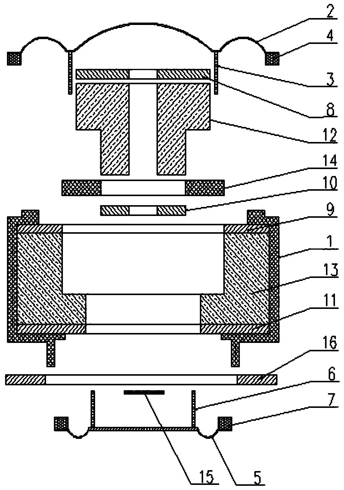
[0037] refer to Figure 1-2 , which shows the specific structure of the first preferred embodiment of the present invention, the specific implementation is: the first magnet 12 is provided with a first magnetically conductive plate 8, and the first magnet 12 is provided with a third magnetically conductive plate 8. Plate 10, the second magnet 13 is arranged on the outer periphery of the first magnet 12, is fixed with an annular connecting piece 14 between the first magnet 12 and the second magnet 13, is provided with the second magnetically conductive plate 9 above the second magnet 13, the second The second magnet 13 is provided with a fourth magnetically conductive plate 11, a first accommodating cavity 801 is formed between the outer circumference of the first magnetically conductive plate 12 and the inner circumference of the second magnetically conductive plate 13, and the third magnetically conductive plate 10 A second accommodating cavity 1001 is formed between the oute...

Embodiment 2

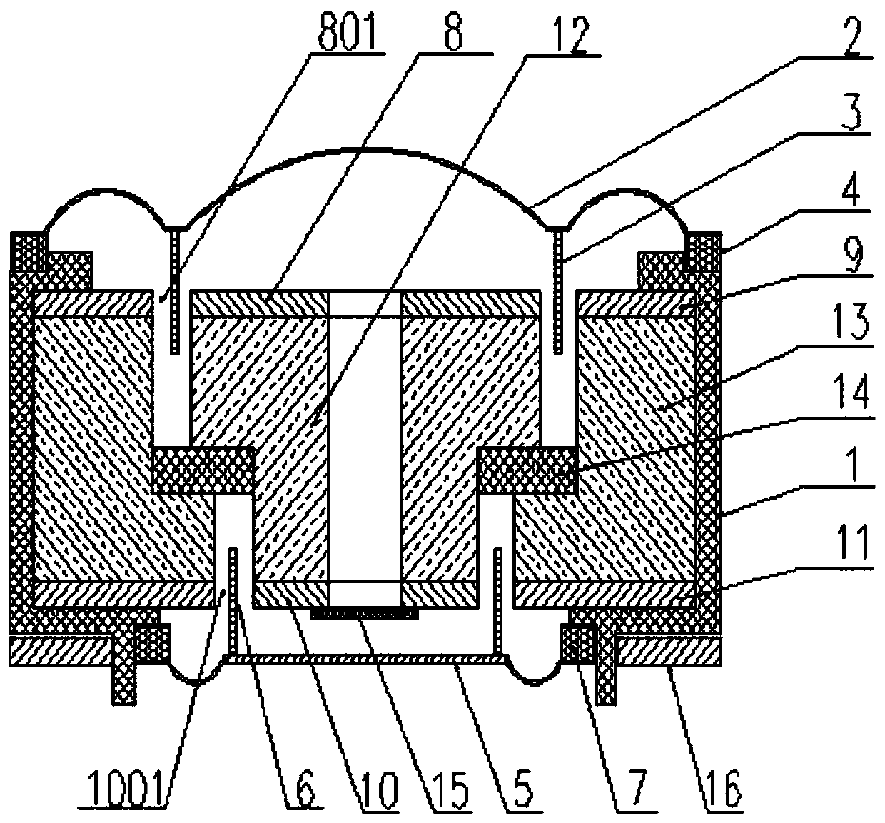
[0041] refer to image 3 , which shows the specific structure of the second preferred embodiment of the present invention, the specific implementation is: the first magnet 12 is provided with a first magnetically conductive plate 8, and the bottom of the first magnet 12 is provided with a third magnetically conductive Plate 10, the second magnet 13 is arranged on the outer periphery of the first magnet 12, is fixed with an annular connecting piece 14 between the first magnet 12 and the second magnet 13, is provided with the second magnetically conductive plate 9 above the second magnet 13, the second Below the second magnet 13 is provided with a fourth magnetically conductive plate 11, a first accommodating cavity 801 is formed between the outer circumference of the first magnetically conductive plate 8 and the inner circumference of the second magnetically conductive plate 9, and the third magnetically conductive plate 10 A second accommodating cavity 1001 is formed between t...

Embodiment 3

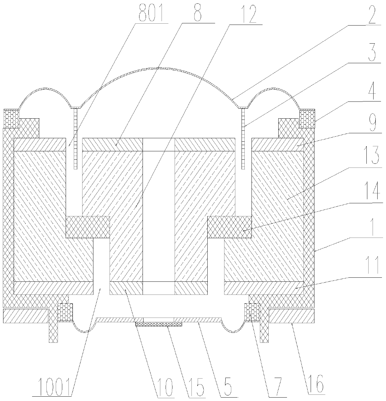
[0045] refer to Figure 4 , which shows the specific structure of the third preferred embodiment of the present invention, the specific implementation is: the first magnet 12 is provided with a first magnetically conductive plate 8, and the bottom of the first magnet 12 is provided with a third magnetically conductive Plate 10, the second magnet 13 is arranged on the outer periphery of the first magnet 12, is fixed with an annular connecting piece 14 between the first magnet 12 and the second magnet 13, is provided with the second magnetically conductive plate 9 above the second magnet 13, the second Below the second magnet 13 is provided with a fourth magnetically conductive plate 11, a first accommodating cavity 801 is formed between the outer circumference of the first magnetically conductive plate 8 and the inner circumference of the second magnetically conductive plate 9, and the third magnetically conductive plate 10 A second accommodating cavity 1001 is formed between t...


PUM


Abstract

The invention discloses a loudspeaker with a novel double-magnetic structure. The loudspeaker comprises a first voice diaphragm, a second voice diaphragm, a first voice coil, a second voice coil, a first copper ring, a second copper ring, a first concentrating flux plate, a second concentrating flux plate, a third concentrating flux plate, a fourth concentrating flux plate, a first magnet, a second magnet, an annular connecting block, a support, tuning paper and a PCB. A first concentrating flux plate is arranged on the first magnet, a third concentrating flux plate is arranged below the firstmagnet, the second magnet is arranged on the periphery of the first magnet, and the first magnet and the second magnet are fixed through an annular connecting block. The invention follows the acoustic principle so that the structure is excellent. The key point is that upper and lower voice diaphragms simultaneously pronounce; the two voice diaphragms are matched in a large-small mode, the defectsof low frequency and high frequency can be overcome at the same time, the frequency response range of the loudspeaker is wider, meanwhile, the magnetic circuit design enables the magnetic field intensity of the two voice diaphragms to be higher, the support and the magnetic set part adopt the injection molding process, and therefore the electroacoustic performance is more excellent, the process is simplified, and consistency is better.

Description

technical field [0001] The invention relates to an electroacoustic device, in particular to a novel double magnetic structure loudspeaker. Background technique [0002] The quality of the speaker's structure determines its sound quality. Now the speakers on the market have their own characteristics, and a single sound film with a traditional structure is generally used to produce sound. The range of sound performance is not wide enough, that is, the high and low frequencies cannot be well coordinated. Under such circumstances, it is necessary to develop a speaker with a new structure to better improve the sound quality. Contents of the invention [0003] The technical problem to be solved by the invention is a new double magnetic structure loudspeaker, which is easy to operate and can effectively improve the sound quality. [0004] The present invention is achieved through the following technical solutions: a novel double magnetic structure loudspeaker, comprising a first...

Claims


Application Information

Patent Timeline
Patent Type & Authority Applications(China)
IPC IPC(8): H04R9/06H04R9/02
CPCH04R9/02H04R9/06H04R2400/11
Inventor 陈新得
Owner 陈新得
Why Eureka
Try Eureka