
Optical fiber sensor structure for partial discharge of transformers and demodulating method and monitoring method thereof

A fiber optic sensor, partial discharge technology, applied in the direction of using optical methods for testing, instruments, measuring electricity, etc., can solve the problems of weak anti-electromagnetic interference, poor stability, low precision, etc., to achieve strong anti-electromagnetic interference, improve consistency High performance and high precision

Active Publication Date: 2019-02-15
WUHAN UNIV OF TECH
View PDF5 Cites 2 Cited by
  • Summary
  • Abstract
  • Description
  • Claims
  • Application Information

AI Technical Summary

Problems solved by technology

At present, the monitoring methods for partial discharge of power transformers include pulse current method and radio frequency measurement method. However, these traditional methods have many problems such as weak anti-electromagnetic interference ability, poor stability and low precision.

Method used


Image

  • Optical fiber sensor structure for partial discharge of transformers and demodulating method and monitoring method thereof
  • Optical fiber sensor structure for partial discharge of transformers and demodulating method and monitoring method thereof
  • Optical fiber sensor structure for partial discharge of transformers and demodulating method and monitoring method thereof

Examples


Embodiment Construction

[0028] The technical solutions of the present invention will be described below in conjunction with the accompanying drawings and embodiments.

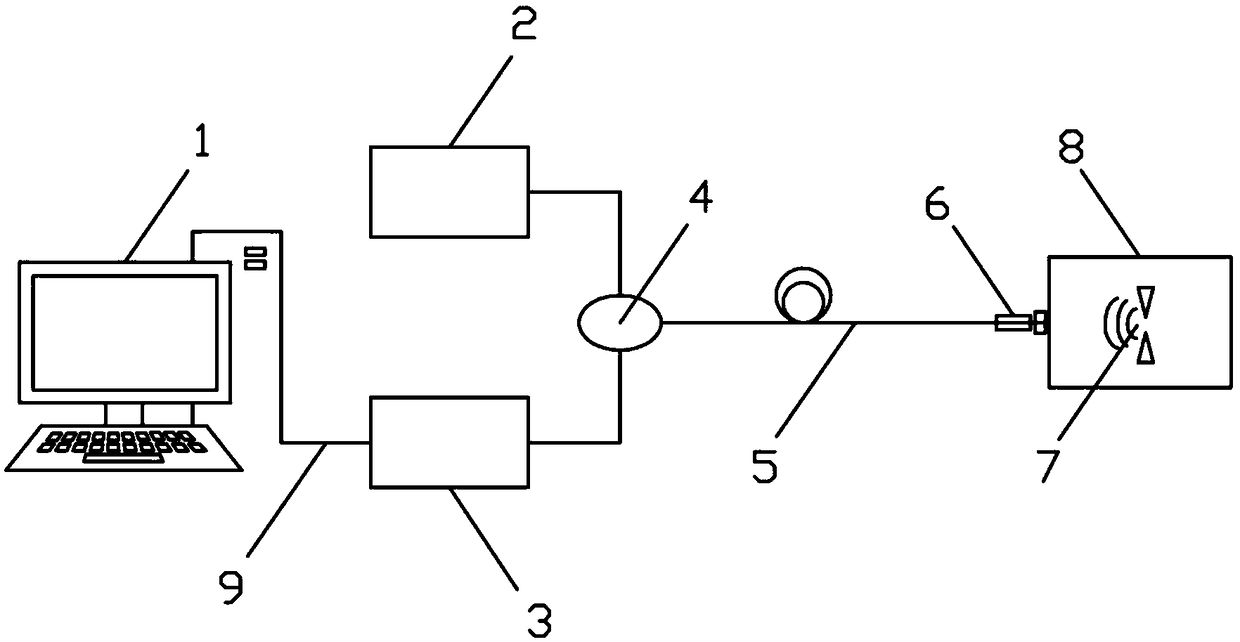
[0029] like figure 1 As shown, the optical fiber sensor structure of transformer partial discharge in the present invention includes a computer 1, a light source module 2, a signal demodulation unit 3, an optical coupler 4, an optical fiber F-P acoustic sensor 6 and a transformer 8, and the optical coupler 4 passes through an optical cable 5 They are respectively connected to the light source module 2, the signal demodulation unit 3 and the optical fiber F-P acoustic sensor 6, the signal demodulation unit 3 is connected to the computer 1 through the data line 9, and the optical fiber F-P acoustic sensor 6 is installed on the outside of the transformer 8 using a support beam diaphragm structure . The above constitutes the basic structure of the present invention.

[0030] With such a structural setting, its working principle: the opt...


PUM


Abstract

The invention relates to the technical field of optical fiber sensing monitoring and diagnosis application, and especially refers to an optical fiber sensor structure for partial discharge of transformers. The optical fiber sensor structure comprises a computer, a light source module, a signal demodulation unit, an optical coupler, an optical fiber F-P acoustic sensor and a transformer. The optical coupler is connected to the light source module, the signal demodulation unit and the optical fiber F-P acoustic sensor through an optical cable. The signal demodulation unit is connected to the computer through a data line. The optical fiber F-P acoustic sensor is installed outside the transformer by a support beam type diaphragm structure. By using an optical fiber F-P acoustic sensor probe prepared by the MEMS technology, the consistency and mass production are improved. The optical fiber F-P acoustic sensor has the advantages such as small size, strong anti-electromagnetic-interference ability, wide frequency response range and high accuracy. By means of multi-point monitoring, a fault expert diagnosis and alarm device can locate the position of local discharge inside the transformerand monitor the discharge time and quantity.

Description

technical field [0001] The invention relates to the technical field of optical fiber sensing monitoring and diagnosis application, in particular to a structure of an optical fiber sensor for partial discharge of a transformer, a demodulation method of a signal demodulation unit and a monitoring method of an optical fiber sensor, and in particular to a transformer prepared based on MEMS technology. Background technique [0002] The power transformer is one of the most important electrical operation core equipment in the entire modern electric power industry system. It is the basis for ensuring the reliability of power supply. Much depends on its insulation state. Long-term studies have shown that the end of life of most transformers is due to the loss of the insulation capacity of the application, and the most important factor affecting the insulation capacity is the winding temperature during transformer operation. In addition, the main characteristic of the sudden fault of...

Claims


Application Information

Patent Timeline
Patent Type & Authority Applications(China)
IPC IPC(8): G01R31/12
CPCG01R31/1218G01R31/1227
Inventor 童杏林潘旭刘访邓承伟张翠
Owner WUHAN UNIV OF TECH
Learn More