
Constant-temperature humidification device

A technology of constant temperature device and chemical device, applied in the field of medical equipment, can solve problems such as temperature rise, electric shock by electric leakage, and inability to control temperature, and achieve the effect of avoiding humidity loss or temperature loss and improving time.

Active Publication Date: 2019-10-15
SHENZHEN HOSPITAL OF SOUTHERN MEDICAL UNIV
View PDF5 Cites 0 Cited by
  • Summary
  • Abstract
  • Description
  • Claims
  • Application Information

AI Technical Summary

Problems solved by technology

[0003] Existing gas humidification devices usually use built-in heating. For example, a heating rod is installed in the humidification bottle to directly heat the liquid (such as water) in the humidification bottle. However, this method cannot effectively control the water temperature and is prone to sudden temperature changes. Rising problem, and there are certain safety hazards (such as circuit short circuit)
[0004] In addition, there is also a heating device installed at the bottom of the humidification bottle to heat the humidification bottle. However, this heating device has a simple structure and is prone to damage, electric leakage, electric shock or burns and other safety hazards, and it is also impossible to control the temperature.

Method used


Image

  • Constant-temperature humidification device
  • Constant-temperature humidification device
  • Constant-temperature humidification device

Examples


Embodiment Construction

[0042] The following will clearly and completely describe the technical solutions in the embodiments of the present invention with reference to the accompanying drawings in the embodiments of the present invention. Obviously, the described embodiments are only some, not all, embodiments of the present invention. Based on the embodiments of the present invention, all other embodiments obtained by persons of ordinary skill in the art without creative efforts fall within the protection scope of the present invention.

[0043] It should be noted that, in the case of no conflict, the embodiments of the present invention and the features in the embodiments can be combined with each other.

[0044] The present invention will be further described below in conjunction with the accompanying drawings and specific embodiments, but not as a limitation of the present invention.

[0045] An exemplary embodiment of the present invention, such as Figure 1~2 As shown, a constant temperature h...


PUM


Abstract

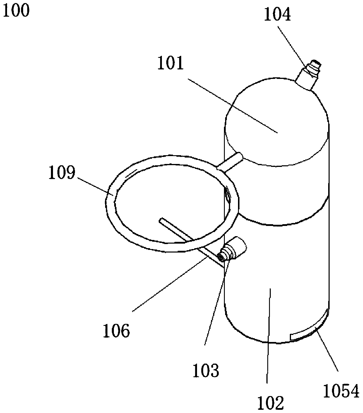
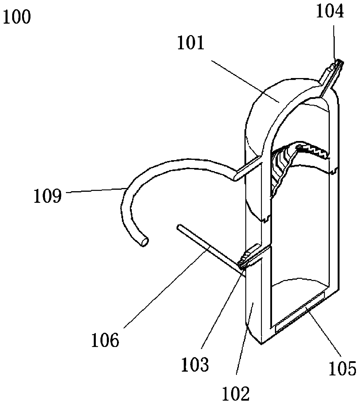
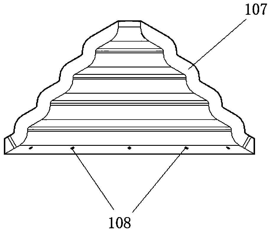
The invention relates to a constant-temperature humidification device, comprising: a gas source inlet disposed at the middle and lower part of one side of the device; a gas source outlet at the middleand upper part of the other side of the device; a thermostat disposed at the bottom of the device; a power supply connection line connected to the thermostat and penetrating the device. The device isadvantageous in that the thermostat performs mild heating and thermal insulation for the device to avoid a sharp rise in temperature; a baffle structure with a unique structure is arranged in the humidification device, can prolong the residence time of gas in the device, and can avoid humidity or temperature loss of heated and humidified gas in a flowing process.

Description

technical field [0001] The invention relates to the technical field of medical devices, in particular to a constant temperature humidification device. Background technique [0002] During some treatments, it is necessary to warm and humidify the gas delivered to the patient in order to assist the patient to breathe. [0003] Existing gas humidification devices usually use built-in heating. For example, a heating rod is installed in the humidification bottle to directly heat the liquid (such as water) in the humidification bottle. However, this method cannot effectively control the water temperature and is prone to sudden temperature changes. There is a problem of rising, and there are certain safety hazards (such as circuit short circuit). [0004] In addition, there is also a heating device installed at the bottom of the humidification bottle to heat the humidification bottle, but this kind of heating device has a simple structure and is prone to damage, electric leakage, ...

Claims


Application Information

Patent Timeline
Patent Type & Authority Applications(China)
IPC IPC(8): A61M16/16
CPCA61M16/16
Inventor 徐建国朱颖窦守坤杨超陶淑慧
Owner SHENZHEN HOSPITAL OF SOUTHERN MEDICAL UNIV
Learn More