Foam concrete distributing machine and distributing method thereof

A foam concrete and placing machine technology, which is applied to ceramic molding machines, supply devices, manufacturing tools, etc., can solve the problems of reducing the impact force of foam concrete, uneven size and unevenness of pores, etc., to improve quality and avoid uneven density. Effect

Pending Publication Date: 2019-10-15
卓建科
View PDF0 Cites 4 Cited by
  • Summary
  • Abstract
  • Description
  • Claims
  • Application Information

AI Technical Summary

Problems solved by technology

[0003] In order to solve the above problems, the present invention designs a foam concrete distribution machine and its distribution method, which can pour foam concrete into the pouring area in a scanning manner, and through the setting of the buffer and decompression device, it can greatly reduce the cost caused by the supply. The impact of the foamed concrete sprayed from the material pipe on the foamed concrete that has been poured in the pouring area can effectively prevent air from entering the foamed concrete, thereby avoiding the uneven size of the pores inside the foamed concrete facility after pouring The phenomenon, and it does not need to move the feed pipe in the foam concrete that has been poured in the pouring area, so as to avoid the phenomenon of disturbing the foam concrete, that is, it can effectively avoid the phenomenon of uneven density of the foam concrete, and then can improve the foam quality. The quality of concrete facilities after pouring

Method used


Image

  • Foam concrete distributing machine and distributing method thereof
  • Foam concrete distributing machine and distributing method thereof
  • Foam concrete distributing machine and distributing method thereof

Examples


Embodiment approach 1

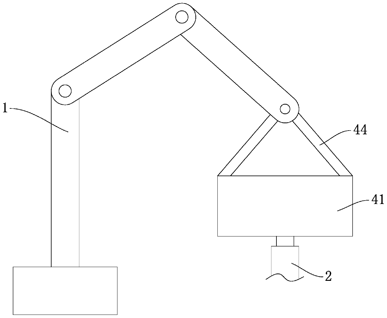
[0029] A foam concrete distributing machine includes a mechanical arm 1. The front end of the mechanical arm 1 is fixed with a buffer pressure reducing device for reducing the impact force of the foam concrete, and the buffer pressure reducing device is connected with a supply for conveying the foam concrete to the buffer pressure reducing device. The material pipe 2, the end of the supply pipe 2 away from the buffer pressure reducing device is connected to the discharge port of the foam concrete production equipment. The buffer pressure reducing device is used to pour the foam concrete into the pouring area 3; the robot arm in the above content is an existing There is technology, so I won't repeat it here.

[0030] The buffer decompression device includes a first material box 41 with an upper end opening and a cavity provided therein, a first feed pipe 42 is communicated with the bottom of the first material box 41, and the first feed pipe 42 is connected to the feed pipe 2; A f...

Embodiment approach 2

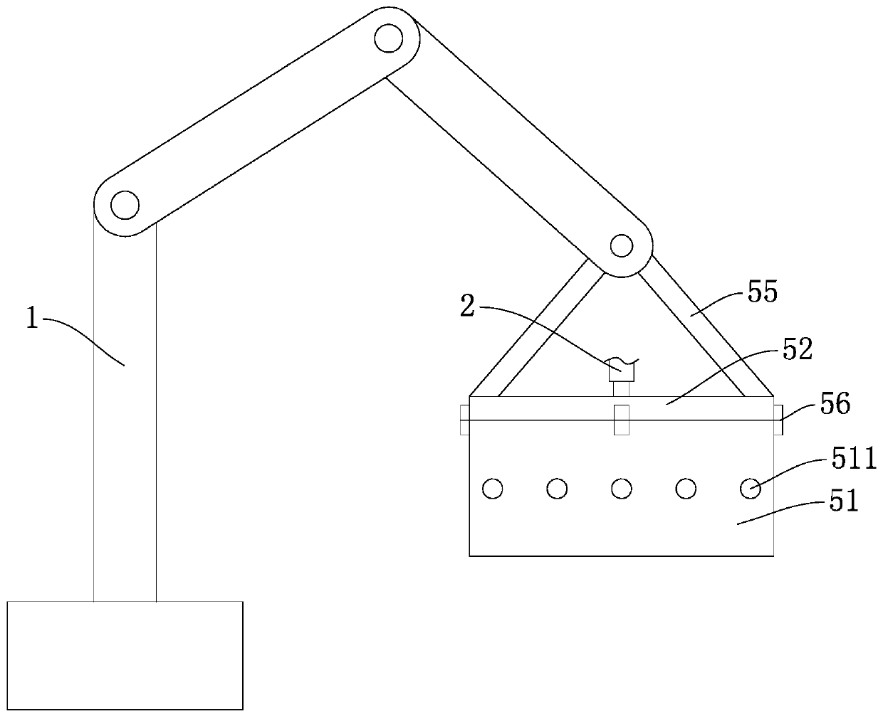
[0037] The difference from the first embodiment is that the cushioning and decompression device includes a second material box 51 with an open upper end and a cavity provided therein. A first cover plate 52 and a first cover plate 52 are fixed on the upper end surface of the second material box 51. There is a second feed pipe 53 connected to the center, the second feed pipe 53 is connected to the feed pipe 2, and the upper peripheral wall of the second feed box 51 is provided with a plurality of first discharge channels 511 evenly distributed in the circumferential direction; A second shaft sleeve 54 is provided above a cover plate 52. The second shaft sleeve 54 is connected to the front end of the mechanical arm 1 by a pin shaft. The outer walls of both sides of the second shaft sleeve 54 are welded and fixed with second connecting rods 55, two The end of the second connecting rod 55 away from the second shaft sleeve 54 is welded and fixed to the upper end surfaces of the left ...

Embodiment approach 3

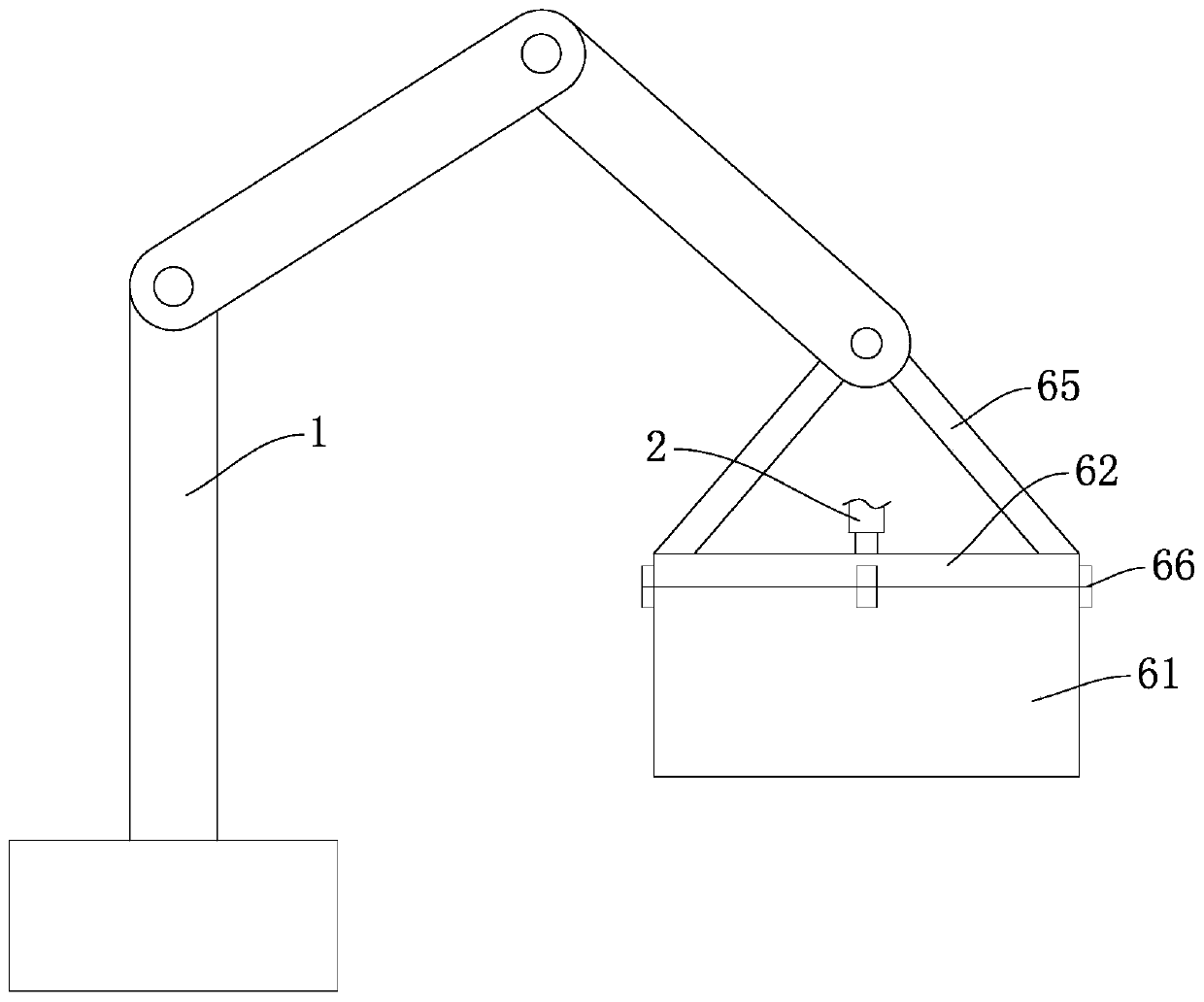
[0042] The difference from the first embodiment is that the cushioning and decompression device includes a third material box 61 with an open upper end and a cavity provided therein, a second cover 62 is fixed on the upper end surface of the third material box 61, and the third material box 61 An upward protrusion 611 is provided in the middle of the inner bottom part of the protrusion 611, and a groove 612 is provided at the upper end of the protrusion 611. The second cover plate 62 located directly above the groove 612 is connected with a third feeding pipe 63. 63 is connected to the feeding pipe 2, and the bottom of the third material box 61 located outside the protrusion 611 is provided with a number of second discharge channels 613 evenly distributed in the circumferential direction; a third shaft is provided above the second cover 62 A sleeve 64, the third shaft sleeve 64 is connected with the front end of the mechanical arm 1 by a pin, the third shaft sleeve 64 is welded ...


PUM


Abstract

The invention discloses a foam concrete distributing machine and a distributing method thereof. The machine comprises a mechanical arm, wherein a buffer decompression device is fixed on the front endof the mechanical arm; and the buffer decompression device communicates with a feeding pipe. The method comprises the following steps: 1, using foam concrete production equipment to convey foam concrete into the buffer decompression device; 2, using the mechanical arm to drive the buffer decompression device to move on a pouring area along the S-shaped direction; 3, determining whether a layer more needs to be poured or not by a worker, if yes, proceeding to step 4, if no, stopping the foam concrete production equipment from conveying the foam concrete into the buffer decompression device, andstopping the work of the mechanical arm; and 4, stopping the foam concrete production equipment from conveying the foam concrete into the buffer decompression device, using the mechanical arm to drive the buffer decompression device to move to the starting point of the last pouring, and returning to the step 1. By means of the machine and the method, the quality of a foamed concrete facility after pouring is improved.

Description

Technical field [0001] The invention belongs to the technical field of foam concrete distributing devices, and in particular relates to a foam concrete distributing machine and a distributing method thereof. Background technique [0002] At present, when using foam concrete to pour foam concrete facilities, there are generally two ways. The first method is to spray the foam concrete into the pouring area by hand-held pouring pipes. However, in this way, due to the spouting of the pouring pipes The foamed concrete has a greater impact force. As a result, the foamed concrete sprayed from the pouring pipe can easily bring air into the pouring area, which will cause uneven pore sizes in the foamed concrete facility after pouring. This will further affect the quality of the foam concrete facility, and when the foam concrete sprayed from the pouring pipe impacts the foam concrete that has been poured into the pouring area, it will disturb the foam concrete that has been poured into the...

Claims


Application Information

Patent Timeline
Patent Type & Authority Applications(China)
IPC IPC(8): B28B1/50B28B13/02
CPCB28B1/50B28B13/02
Inventor 卓建科
Owner 卓建科
Why Eureka
Try Eureka