
Self-adjusting truck front flow guiding device and control method thereof

A diversion device and self-adjusting technology, applied in the direction of car body, vehicle parts, streamlined body, etc., can solve the problems of increasing resistance, difficult to deal with the change of starting resistance coefficient, unsatisfactory diversion effect, etc.

Pending Publication Date: 2019-10-15
JILIN UNIV
View PDF6 Cites 6 Cited by
  • Summary
  • Abstract
  • Description
  • Claims
  • Application Information

AI Technical Summary

Problems solved by technology

A large part of the reason is that there is a large gap and vertical height difference between the truck cab and the cargo box (carriage). The former causes a large airflow separation area around the end of the cab when the incoming flow passes through the gap. And collide with the side wind incoming flow to form an irregularly moving vortex, resulting in increased resistance; the latter will cause the incoming flow to directly contact the front of the cargo box after passing through the cab, forming a positive pressure zone, thereby increasing the resistance
[0003] In the prior art, the diversion device is generally a fixed structure, which can only guide the flow or delay the separation of the eddy current in some water areas, and it is difficult to deal with the change of the starting drag coefficient at different vehicle speeds; the diversion effect is not ideal

Method used


Image

  • Self-adjusting truck front flow guiding device and control method thereof
  • Self-adjusting truck front flow guiding device and control method thereof
  • Self-adjusting truck front flow guiding device and control method thereof

Examples


Embodiment Construction

[0072] The present invention will be further described in detail below in conjunction with the accompanying drawings, so that those skilled in the art can implement it with reference to the description.

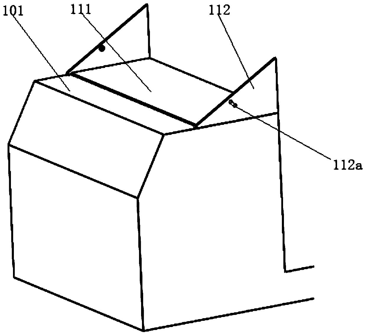
[0073] like figure 1 As shown, the present invention provides a self-adjusting truck front deflector, which mainly includes: a deflector liner 110, a deflector 120, a first telescopic rod 130, a fixed guide rail 140, a telescopic deflector 150, a second Two telescoping rods 160, a driving device and a transition closure cover.

[0074] like figure 2 As shown, the shroud liner 110 includes: a bottom plate 111 and two side liners 112 . The bottom plate 111 is fixedly installed on the top plate 101 of the driver's cab; the two side lining plates 112 are fixedly connected to the left and right sides of the bottom plate 111 vertically upward respectively. Wherein, the side liner 112 is triangular.

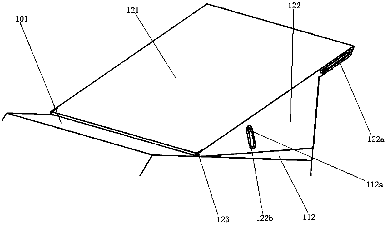
[0075] like image 3 As shown, the wind deflector 120 is semi-enclosed and a...


PUM


Abstract

The invention discloses a self-adjusting truck front guiding device. The self-adjusting truck front guiding device comprises a flow guiding cover lining plate, a flow guiding cover, two first slidinggrooves, two first telescopic rods, two fixed guiding rails, two telescopic flow guiding plates, transition sealing covers, and a driving device, wherein the flow guiding cover lining plate is fixedlyarranged on a top plate of a cab, the flow guiding cover is arranged on the outer side of the flow guiding cover lining plate in a surrounding manner; the two first sliding grooves are symmetricallyarranged on the two sides of the flow guiding cover correspondingly; the two first telescopic rods are fixedly arranged on the left side and the right side of a back plate of the cab in the vertical direction correspondingly, and the movable ends of the first telescopic rods are arranged in the first sliding grooves in a matched mode; the two fixed guiding rails are symmetrically and fixedly arranged on the left side and the right side of the front part of a carriage in the vertical direction; the two telescopic guiding plates are symmetrically arranged between the cab and the carriage correspondingly; the transition sealing covers support two second telescopic rods in a covering mode, and are connected between the flow guiding cover, the two telescopic flow guiding plates and the fixed guide rails; and the driving device is used for driving the movable ends of the first telescopic rods to extend out or retract, so that the included angle between a main flow guiding plate of the flow guiding cover and the top plate of the cab is increased or reduced.

Description

technical field [0001] The invention belongs to the technical field of truck front deflectors, in particular to a self-adjusting truck front deflector and a control method thereof. Background technique [0002] When the truck is running at high speed, the aerodynamic resistance accounts for a large proportion of the resistance it encounters. A large part of the reason is that there is a large gap and vertical height difference between the truck cab and the cargo box (carriage). The former causes a large airflow separation area around the end of the cab when the incoming flow passes through the gap. And it collides with the side wind incoming flow to form an irregularly moving eddy current, resulting in increased resistance; the latter will cause the incoming flow to directly contact the front of the cargo box after passing through the cab, forming a positive pressure zone, thereby increasing the resistance. [0003] In the prior art, the deflector is generally a fixed struc...

Claims


Application Information

Patent Timeline
Patent Type & Authority Applications(China)
IPC IPC(8): B62D35/00
CPCB62D35/00Y02T10/82
Inventor 胡兴军万沁林辛俐张扬辉刘江刘一尘王靖宇张志强王漠耿亚林李天鸿金少刚
Owner JILIN UNIV
Features
  • Generate Ideas
  • Intellectual Property
  • Life Sciences
  • Materials
  • Tech Scout
  • Unparalleled Data Quality
  • Higher Quality Content
  • 60% Fewer Hallucinations
Learn More