Handpiece assembly, air duct system and fan

A component and machine head technology, which is applied in the field of household appliances, can solve the problems of reducing the air volume of the bladeless fan outlet, reducing the wind feeling of the user, and reducing the noise, so as to enhance the wind feeling experience, reduce the noise problem, and reduce the processing cost.

Pending Publication Date: 2020-07-10
GREE ELECTRIC APPLIANCES INC
View PDF0 Cites 2 Cited by
  • Summary
  • Abstract
  • Description
  • Claims
  • Application Information

AI Technical Summary

Problems solved by technology

Due to the long length of the air outlet duct, in order to reduce the loss of the airflow along the way in the air outlet duct, the above-mentioned air wall structure is generally designed as an arc structure, which has an arc-shaped guide surface. When two arc-shaped air walls When set up oppositely, the air outlet is located in the middle of the two closed ones as mentioned above, so that when the airflow converges towards the air outlet, the diversion of part of the airflow will cause convection, which reduces the air output of the bladeless fan outlet, and also It is easy to cause noise and weaken the user's sense of wind

Method used


Image

  • Handpiece assembly, air duct system and fan
  • Handpiece assembly, air duct system and fan
  • Handpiece assembly, air duct system and fan

Examples


Embodiment 1

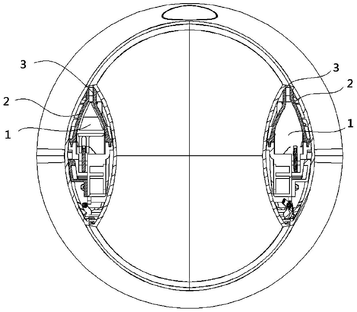
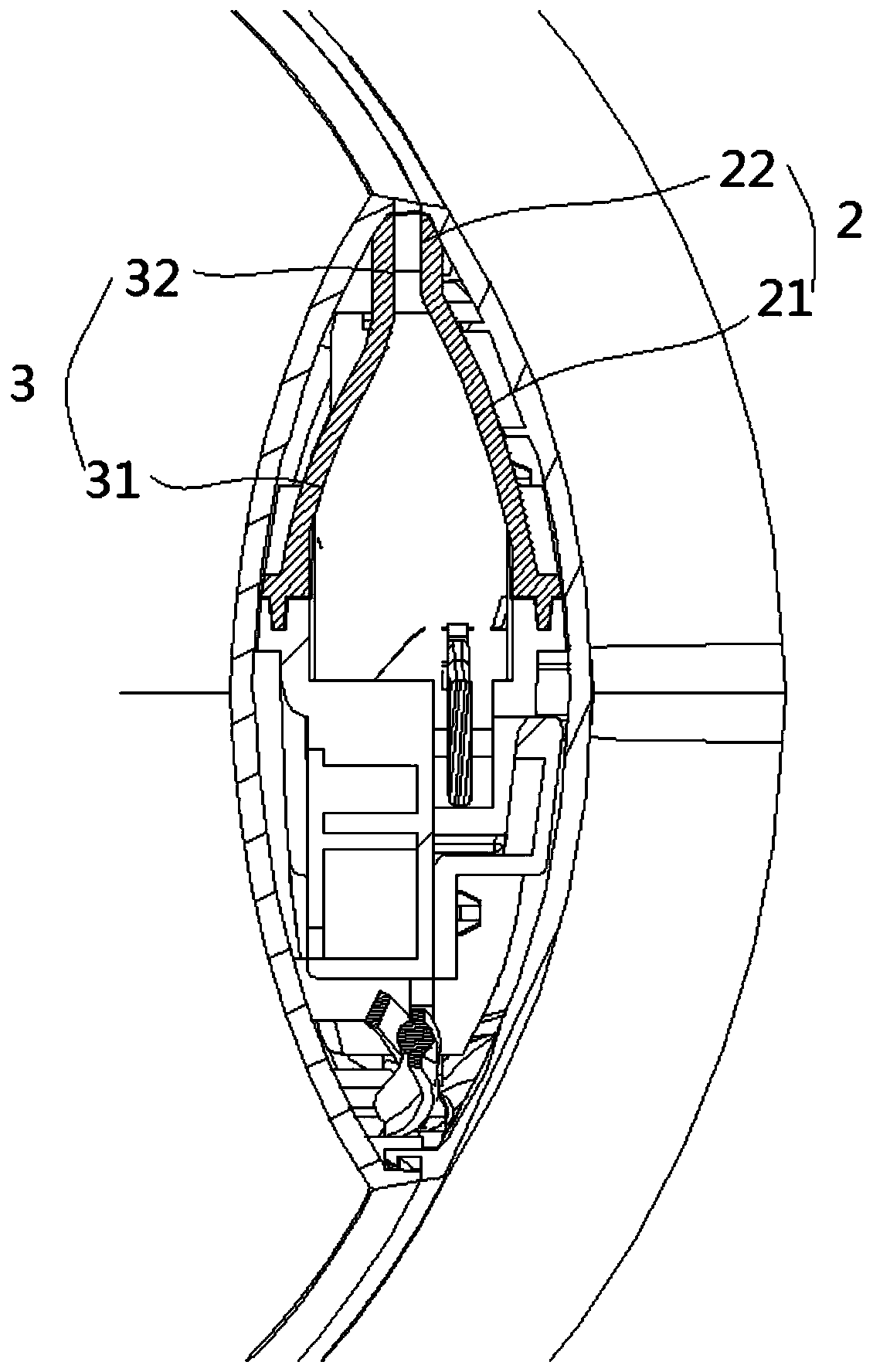
[0058] Figure 1 to Figure 5 As shown, a head assembly provided in this embodiment includes an air outlet duct 1 and an air guide plate, and several air guide plates form a plurality of air outlet parts at intervals between the air outlet duct, and the air outlet parts have mutually oppositely arranged The first wind wall 2 and the second wind wall 3, wherein: the first wind wall 2 includes a first arc-shaped guide surface 21 and a first outlet surface following the first arc-shaped guide surface 21 along the airflow direction 22; the second wind wall 3 includes a second arc-shaped guide surface 31 and a second outlet surface 32 connected to the second arc-shaped guide surface 31 along the airflow direction; the first outlet surface 22 and the second outlet surface A wind outlet gap is formed between the flow surfaces 32, and along the flow direction of the airflow, the extension surface of the first arc-shaped flow guide surface 21 meets the second flow surface 32, and the ex...

Embodiment 2

[0075] Such as Figure 6 to Figure 7 As shown, a kind of air duct system provided for this embodiment includes: the head assembly in the above-mentioned embodiment 1; the air inlet assembly 4 is installed under the power device 5, and the external air flows into the power device 5 through the air inlet assembly 4 Middle; the deflector assembly 6 is covered on the power unit 5, and its air outlet is connected to the air outlet duct 1.

[0076]Specifically, such as Figure 7 As shown in the figure, the air inlet assembly 4 includes: an air inlet wall 41, which is ring-shaped, and several air inlet structures are arranged on it. Enter the air duct system through the air inlet hole. Because the initial air intake direction is basically parallel to the axial direction of the air duct, several deflectors 42 are installed in the middle of the air inlet wall 41. The deflectors 42 are vertically arranged and have a certain air intake gap between them. Plate-shaped structure, the ext...

Embodiment 3

[0080] Such as Figure 8 As shown, it is a fan provided in this embodiment, specifically a bladeless fan, which includes the air duct system in Embodiment 2 above, which specifically includes the air outlet duct 1, the air inlet assembly 4, the power The device 5 and the corresponding flow guide assembly 6 have all the technical advantages thereof, which will not be repeated here.


PUM


Abstract

The invention provides a handpiece assembly, an air duct system and a fan. The handpiece assembly comprises an air outlet duct and air guide plates; the air outlet duct is divided into a plurality ofair outlet parts by the multiple air guide plates, and each air outlet part is provided with a first air wall and a second air wall which are arranged opposite to each other; each first air wall comprises a first arc-shaped flow guide surface and a first flow outlet surface which is connected to the first arc-shaped flow guide surface in the air flow direction; each second air wall comprises a second arc-shaped flow guide surface and a second flow outlet surface which is connected to the second arc-shaped flow guide surface in the air flow direction; an air outlet gap is formed between each first flow outlet surface and the corresponding second flow outlet surface; and in the air flow direction, the extension surfaces of the first arc-shaped flow guide surfaces intersect at the second flowoutlet surfaces, and the extension surfaces of the second arc-shaped flow guide surfaces intersect at the first flow outlet surfaces. The handpiece assembly is high in air outlet volume and air pressure.

Description

technical field [0001] The invention relates to the technical field of household appliances, in particular to a head assembly, an air duct system and a fan. Background technique [0002] In the bladeless fan in the prior art, the external airflow is sucked into the fan, and the external airflow is transformed into a high-speed rotating airflow through the power system. The above-mentioned high-speed rotating airflow enters the air outlet assembly in the machine head through the diffusion assembly, and passes The air outlet on the wind assembly flows out to the outside world. [0003] However, the air outlet assembly generally has two air outlet ducts on the left and right, and each air outlet duct is surrounded by two oppositely arranged air wall structures, and the air outlet is a gap reserved at the joint of the two air walls. Part of the airflow entering the air outlet duct flows along the inner surface of the air wall, and at the air outlet, the airflow on both sides of...

Claims


Application Information

Patent Timeline
Patent Type & Authority Applications(China)
IPC IPC(8): F04D29/40F04D29/66F04D25/08
CPCF04D25/08F04D29/403F04D29/667
Inventor 柳洲梁浩饶长健梁文龙黄燕宁王孝忱雷亚阔
Owner GREE ELECTRIC APPLIANCES INC
Why Eureka
Try Eureka