Smoke deflection preventer for gantry industrial furnaces
An industrial furnace and flue gas technology, applied in the combustion method, combustion chamber, baffle and other directions, can solve the problems of flue gas deviation, furnace flue gas deviation, etc., to ensure smooth flow, avoid local temperature is too high and too low, The effect of increasing operational stability and operational flexibility
- Summary
- Abstract
- Description
- Claims
- Application Information
AI Technical Summary
Problems solved by technology
Method used
Image


Examples
Embodiment 1
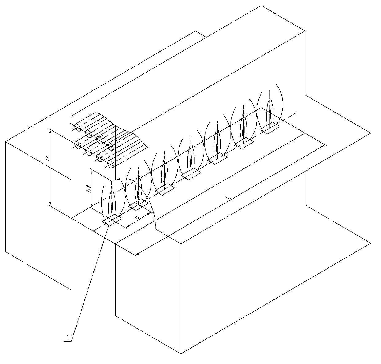
[0033] Such as figure 1 As shown, the radiation section is composed of two relatively independent radiation chambers 6, and the convection section has only one convection chamber. The length of the bottom of the transition section is L, and the distance between the center of the bottom row of furnace tubes in the convection section and the bottom of the transition section is H. The flue gas isolation unit is arranged in the furnace bottom of the transition section so that the center line along the furnace length direction coincides with the center line of the transition section furnace bottom along the furnace length direction. A row of ejectors 2 is arranged in the length direction, and each ejector 2 ejects part of the flue gas in the furnace through a pipe 4. The distance between each ejector 2 is b, and each ejector 2 injects The flue gas width is also b, and the flue gas height h2 injected by each ejector 2 is 0.8×H. In order to ensure that the isolation zone is an area...
Embodiment 2
[0035] Such as figure 2As shown, the radiation section consists of two relatively independent radiation chambers, and the convection section has only one convection chamber. The length of the bottom of the transition section is L, and the distance between the center of the bottom row of furnace tubes in the convection section and the bottom of the transition section is H. The flue gas isolation unit is arranged in the furnace bottom of the transition section so that the center line along the furnace length direction coincides with the center line of the transition section furnace bottom along the furnace length direction. A row of burners 1 is arranged in the length direction, the distance between each burner 1 is a, the flame width of each burner 1 is also a, the flame height h1 of each burner 1 is 0.6×H, and the burner 1 The number of arrangements n=L / a=7. In addition to ensuring that the isolation unit is an area without obvious gaps, when using the burner 1, the flame i...
Embodiment 3
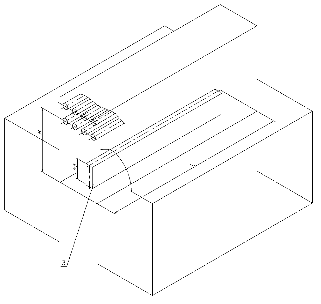
[0037] Such as image 3 As shown, the radiation section consists of two relatively independent radiation chambers, and the convection section has only one convection chamber. The length of the bottom of the transition section is L, and the distance between the center of the bottom row of furnace tubes in the convection section and the bottom of the transition section is H. The flue gas isolation unit is arranged in the furnace bottom of the transition section so that the center line along the furnace length direction coincides with the center line of the transition section furnace bottom along the furnace length direction. An isolation strip 3 is arranged in the length direction, the height h3 of the isolation strip 3 is 0.3×H, and the length of the isolation strip 3 is L. The isolation zone forms an isolation barrier without obvious gaps. Since the wall is denser than the burner and ejector, the isolation effect is obvious. If the isolation zone is too high, it is easy to be...
PUM
 Abstract
Description
Claims
Application Information
 - Generate Ideas
- Intellectual Property
- Life Sciences
- Materials
- Tech Scout
- Unparalleled Data Quality
- Higher Quality Content
- 60% Fewer Hallucinations
Browse by: Latest US Patents, China's latest patents, Technical Efficacy Thesaurus, Application Domain, Technology Topic, Popular Technical Reports.
© 2025 PatSnap. All rights reserved.Legal|Privacy policy|Modern Slavery Act Transparency Statement|Sitemap|About US| Contact US: help@patsnap.com