
Outdoor unit defrosting control method, device and equipment

A control method and technology for outdoor units, applied in mechanical equipment, lighting and heating equipment, fluid heaters, etc., can solve the problems of reduced control accuracy, single defrosting conditions, and increased complexity, and achieve defrosting entry or exit. Single condition, simple judgment of defrosting entry or exit, and ensure the effect of heating experience

Active Publication Date: 2020-07-24
GREE ELECTRIC APPLIANCES INC
View PDF16 Cites 0 Cited by
  • Summary
  • Abstract
  • Description
  • Claims
  • Application Information

AI Technical Summary

Problems solved by technology

Although the more limited judgments, the higher the precision of defrosting entry or exit control, but it is more complicated for system processing
Taking the multi-connected air conditioner as an example, the outdoor unit of the multi-connected air conditioner is equipped with multiple indoor units, and the multiple indoor units are installed in different rooms one by one. The heating temperature and wind gear of the system may be different, so that the status of each indoor unit in operation may be different, which further increases the complexity of controlling the entry or exit of defrosting through multiple limit judgments for multi-connected air conditioners.
[0004] In the related technology of air conditioner defrosting entry or exit control, there is also a very simple control method, that is, during the heating process of the air conditioner, defrosting is performed at regular intervals. This defrosting control method has a single defrosting condition and is suitable for various types of air conditioners. , for example, multi-connected air conditioners and single-unit air conditioners can be well applied, but the problem is that the control accuracy is greatly reduced, and it is often prone to the problem of not defrosting with frost or defrosting without frost

Method used


Image

  • Outdoor unit defrosting control method, device and equipment
  • Outdoor unit defrosting control method, device and equipment
  • Outdoor unit defrosting control method, device and equipment

Examples


Embodiment Construction

[0065] In order to make the purpose, technical solution and advantages of the present application clearer, the technical solution of the present application will be described in detail below. Apparently, the described embodiments are only some of the embodiments of this application, not all of them. Based on the embodiments in the present application, all other implementation manners obtained by persons of ordinary skill in the art without creative efforts fall within the protection scope of the present application.

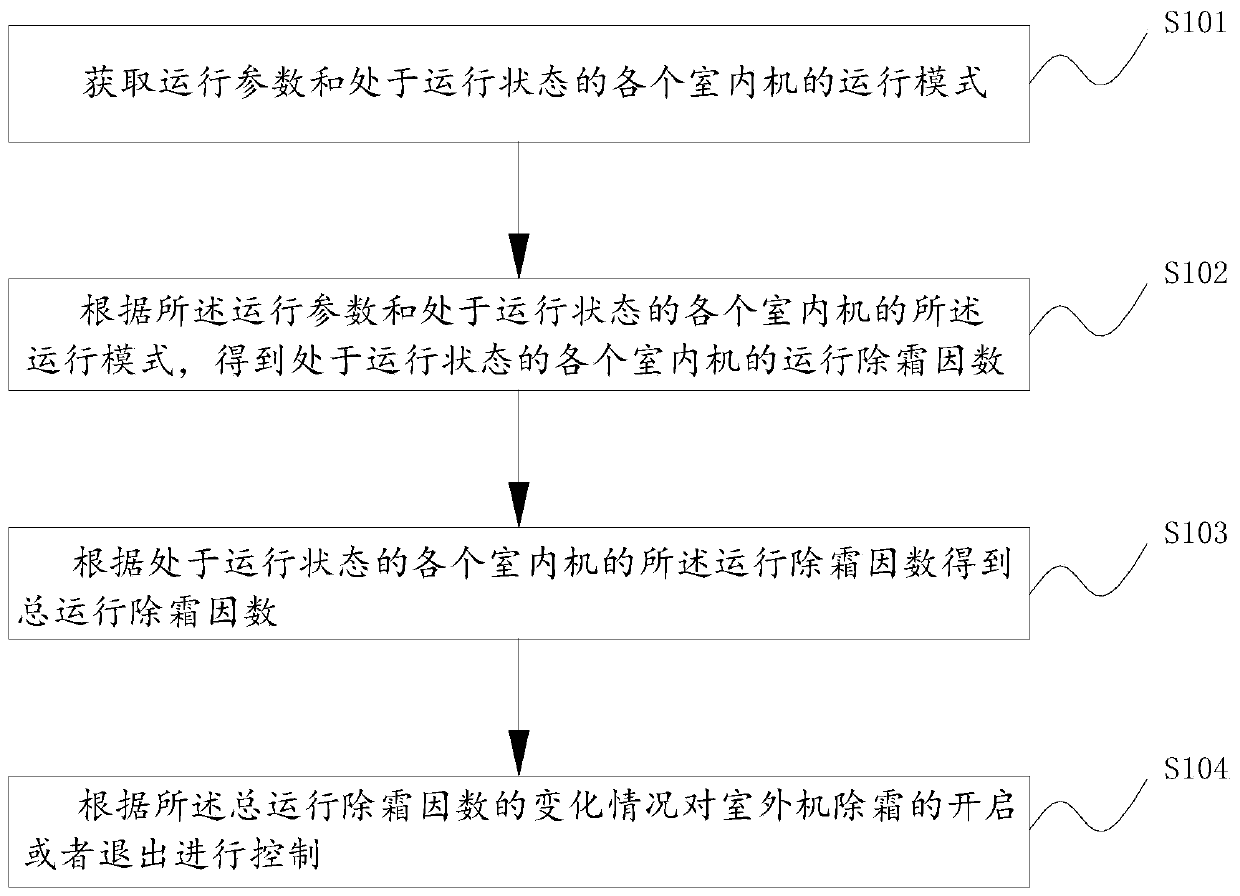
[0066] figure 1 A schematic flow chart of an outdoor unit defrosting control method provided by an embodiment of the present application, as shown in figure 1 As shown, the outdoor unit defrosting control method includes the following steps:

[0067] Step S101, acquiring operating parameters and operating modes of each indoor unit in operating state;

[0068] Step S102, according to the operating parameters and the operating mode of each indoor unit in the ope...


PUM


Abstract

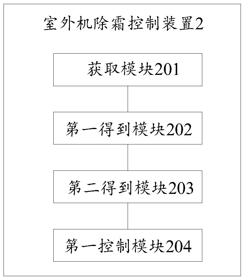
The present invention relates to outdoor machine defrosting control method, device and equipment, and belongs to the field of outdoor machine defrosting control technical field. The method comprises the following steps of acquiring operation parameters and running modes of indoor machines in different running states; obtaining operating defrosting factors of the indoor machines in different running states according to the operation parameters and the running modes of the indoor machines in different running states; obtaining a whole operating defrosting factor according to the operating defrosting factors of the indoor machines in different running states; and control switch-on and switch-off states of the indoor machine defrosting according to changing conditions of the whole operating defrosting factor. According to the outdoor machine defrosting control method, device and equipment, judgement of switch-on and switch-off states of defrosting becomes singularized and simplified, and the precision of switch-on and switch-off states of defrosting can also be guaranteed, thus being better applied to air conditioners of various types.

Description

technical field [0001] The application belongs to the technical field of outdoor unit defrosting control, and in particular relates to an outdoor unit defrosting control method, device and equipment. Background technique [0002] During the heating process of the air conditioner, due to the low outdoor temperature, frost will form on the surface of the heat exchanger of the outdoor unit. Frost formation will lead to deterioration of the heat exchange effect, resulting in a decrease in the heating capacity of the indoor mechanism and affecting the user experience. In order to solve the problem of frosting on the surface of the heat exchanger of the outdoor unit during the heating process, the air conditioners on the market have an automatic defrosting function during the heating process. [0003] In the current defrosting control logic, whether it is an entry condition or an exit condition, in order to achieve higher precision control, a variety of limited judgments are used,...

Claims


Application Information

Patent Timeline
Patent Type & Authority Patents(China)
IPC IPC(8): F24F11/42F24F11/65F24F11/64F24F11/61F24H9/20
CPCF24F11/42F24F11/61F24F11/64F24F11/65F24H9/2007
Inventor 张赛超张仲秋钟明赵振江刘家平
Owner GREE ELECTRIC APPLIANCES INC
Learn More