Split-type crimping MPO (Maximum Power Output) plug

A plug and split technology, applied in the direction of light guide, optics, instruments, etc., can solve the problems of rework and grinding work, easy to break and fail, fiber scrapping and other problems, so as to improve maintenance efficiency and quality, and facilitate rework, grinding and repair work convenient effect

Active Publication Date: 2019-10-15
CHINA AVIATION OPTICAL-ELECTRICAL TECH CO LTD
View PDF7 Cites 4 Cited by
  • Summary
  • Abstract
  • Description
  • Claims
  • Application Information

AI Technical Summary

Problems solved by technology

[0005] 1. Since the limit seat is made into a two-body structure for post-installation, compared with the small-diameter MPO plug (the limit seat is integrated, and the tail is a complete cylinder), the strength of the cylinder at the end of the limit seat decreases. , prone to fracture failure during crimping crimp sleeves and side pull tests
[0006] 2. When assembling the limit seat, the spring should be compressed so that the optical fiber is in a stressed state, and the optical fiber can be unloaded until the outer shell is assembled; similarly, if the end face of the pin has quality problems and needs to be repaired, the outer shell needs to be removed. Remove the body first. Once the limit seat is released from the locking mechanism of the outer shell, the optical fiber will immediately be subjected to the reaction force of the spring. It cannot be removed from the optical cable. During the whole rework process, the optical fiber and the spring are in a state of stress and twisting, which causes great troubles to the rework and grinding work. Improper operation will damage the optical fiber and cause it to be scrapped.

Method used


Image

  • Split-type crimping MPO (Maximum Power Output) plug
  • Split-type crimping MPO (Maximum Power Output) plug
  • Split-type crimping MPO (Maximum Power Output) plug

Examples


Embodiment Construction

[0042] In order to further illustrate the technical means and technical effects adopted by the present invention, a split crimping MPO plug of the present invention will be described in detail below in conjunction with the embodiments.

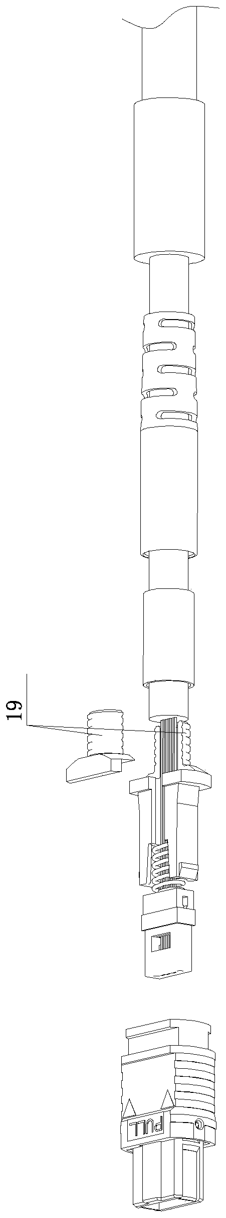
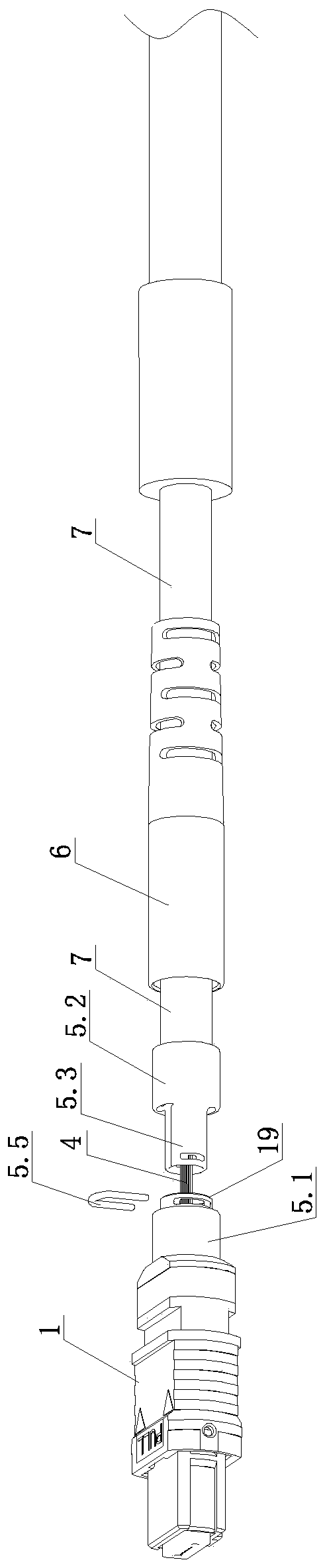
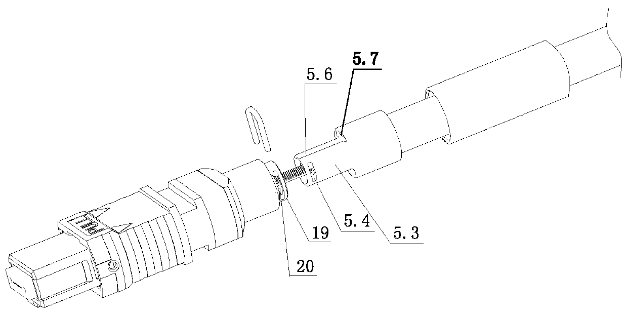
[0043] The MPO plug mainly includes the outer shell 1, the pin part 2, the spring 3, the limit seat, the crimping sleeve 5 and the tail sheath 6. For the convenience of explanation, the end where the pin part is located is defined as the front end. Figure 1-Figure 3 and Figure 5-Figure 9 All are shown with the left end as the front end. In the prior art, the limit seat and the spring in the MPO plug are set on the optical fiber 4 at the front end of the optical cable 7, the spring is wrapped in the limit seat, the front end of the optical fiber is connected to the pin part, and the spring and the limit seat are both set on the pin After the rear end of the component and the limit seat are installed, arrange the tensile element (the tensile ...


PUM


Abstract

The invention relates to a split-type crimping MPO plug, which comprises an outer shell, a pin component, a spring, a limit seat, a crimping sleeve and a tail sheath; the crimping sleeve is a split-type structure, and at least includes a front shell crimped on a tension component distributed on the periphery of the back end shell of the limit seat and a back shell crimped on the cable; the front end of the back shell of the crimping sleeve is connected with a connection piece, which moves axially in the back end shell of the limit seat; the connection piece is inserted in the back end shell ofthe limit seat and locked by a locking mechanism; after the locking mechanism is unlocked, the front shell and the back shell of the crimping sleeve are detachable; and thus, the optical fiber is notstressed when the MPO plug is assembled and disassembled. The split-type crimping sleeve is locked by the locking mechanism and prevented from rotating by a rotation-stopping mechanism, so that the crimping sleeve and the limit seat are unnecessary to be disassembled at the time of repairing and disassembling; the optical fiber is not stressed during the whole assembling and disassembling process; thus, the optical fiber is not distorted; the repairing grinding work is facilitated; and, the optical fiber is not damaged at the time of operating.

Description

technical field [0001] The invention relates to the technical field of optical fiber connectors, in particular to a split crimping MPO plug. Background technique [0002] More and more MPO plugs are used in optical communication systems. Conventional MPO plugs are used in indoor environments, and some equipment manufacturers add protective shells to MPO plugs to apply them in outdoor environments. In order to increase protective shells, It is necessary to exert a large crushing force on the optical cable at the end of the plug, then it is necessary to increase the outer diameter of the optical cable to adjust the optical cable structure and strengthen the compression resistance of the optical cable. At this time, a large-diameter MPO plug is required. [0003] Due to the large diameter of the optical cable, the one-piece limit seat cannot be retracted to the optical cable, so the limit seat is made into a two-body structure, such as figure 1 As shown, when assembling, the c...

Claims


Application Information

Patent Timeline
Patent Type & Authority Applications(China)
IPC IPC(8): G02B6/38
CPCG02B6/381G02B6/3869
Inventor 余永强姚琦武冰洋张长伟
Owner CHINA AVIATION OPTICAL-ELECTRICAL TECH CO LTD
Why Eureka
Try Eureka