Display assembly, display equipment and assembly method of display assembly

A technology of display components and assembly methods, applied in optical components, digital data processing parts, optics, etc., can solve problems such as poor sealing effect, broken screen, increase production cost, etc., to improve display effect, reduce relative displacement, The effect of reducing the chance of damage

Pending Publication Date: 2019-10-15
GUANGZHOU SHIYUAN ELECTRONICS CO LTD +1
View PDF0 Cites 5 Cited by
  • Summary
  • Abstract
  • Description
  • Claims
  • Application Information

AI Technical Summary

Problems solved by technology

[0005] 1. The display panel is positioned with foam between the module plastic frame and the iron front frame. Because the firmness of the foam is not good, and there is a large gap between the transparent protective layer and the display panel, the display panel is soft and easy to Broken objects; during transportation and handling, the display panel is prone to shaking, and the display panel collides with the silicone pad, module plastic frame or transparent protective layer, resulting in broken screen
[0006] 2. The gap between the transparent protective layer and the display panel is relatively large, generally 3mm to 8mm. Due to the large gap and the use of foam sealing, the sealing cannot be tight, and the external water vapor passes through the gap It is easy to enter between the transparent protective layer and the display panel, resulting in water mist on the transparent protective layer and the display panel, affecting the display effect
[0007] 3. In addition, if the gap between the display panel and the transparent protective layer is too large, the relative movement of the display panel due to shaking, deformation, and the transparent protective layer will cause the display panel to be scratched
Especially in some transparent protective layers with double AG surfaces, that is, the side of the transparent protective layer facing the display panel is a rough surface, which is more likely to cause the display panel to be scratched during the relative movement of the display panel and the transparent protective layer; , due to the large gap between the transparent protective layer and the display panel, the edge of the gap between the display panel and the transparent protective layer is sealed by foam. Due to the large area of ​​the sealing surface and the poor sealing effect of the foam, the overall sealing effect is not good. It will cause a large amount of foreign matter (such as dust) to enter the gap, and the foreign matter will be adsorbed on the surface of the transparent protective layer and the surface of the display panel. During the relative movement of the display panel and the transparent protective layer, it is more likely to cause the display panel to be scratched
[0008] 4. The installation and fixation of the display panel is unstable. When it is subjected to external force, the force is uneven, and it is easy to have light leakage, whitening and other display defects when displaying.
[0010] 1. The price of OCA glue is relatively high. To realize the full bonding of the display panel and the transparent protective layer, the cost of each unit will increase by about 800 to 1,000 yuan, which greatly increases the production cost of the product
[0011] 2. OCA glue has strong adhesion, and the display panel and the transparent protective layer are rigidly pasted as a whole. When an external force hits, the external force on the display panel cannot be reduced, which may easily cause the display panel to break; or, the display panel cannot be damaged. The force is transmitted to other parts of the stress point, resulting in uneven force, which will easily damage the display panel at the stress point and cause light leakage
[0012] 3. When the display panel is broken or damaged, it is not easy to peel off the display panel from the transparent protective layer, so that the transparent protective layer cannot be reused
[0013] 4. It is necessary to fully bond the display panel and the transparent protective layer, and the installation process requires high requirements, which further increases the production cost
[0014] Therefore, how to effectively solve quality defects such as broken screens, water mist, abrasions, and light leakage in display devices without increasing production costs is the direction that the inventors have been researching and innovating.

Method used


Image

  • Display assembly, display equipment and assembly method of display assembly
  • Display assembly, display equipment and assembly method of display assembly
  • Display assembly, display equipment and assembly method of display assembly

Examples


no. 1 example

[0154] In the first embodiment, the method specifically includes the following steps:

[0155] placing the display panel on the first platform;

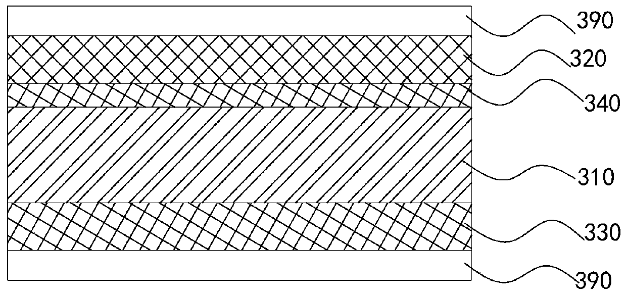
[0156] bonding the first adhesive layer of the adhesive member to the transparent protective layer, and placing the transparent protective layer on the display panel;

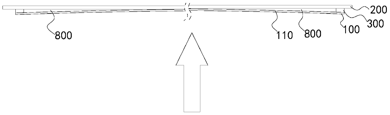
[0157] Under the action of its own gravity or external force, the transparent protective layer at least partially sags its central region toward the display panel side, and at least partially evacuates the air between the transparent protective layer and the display panel;

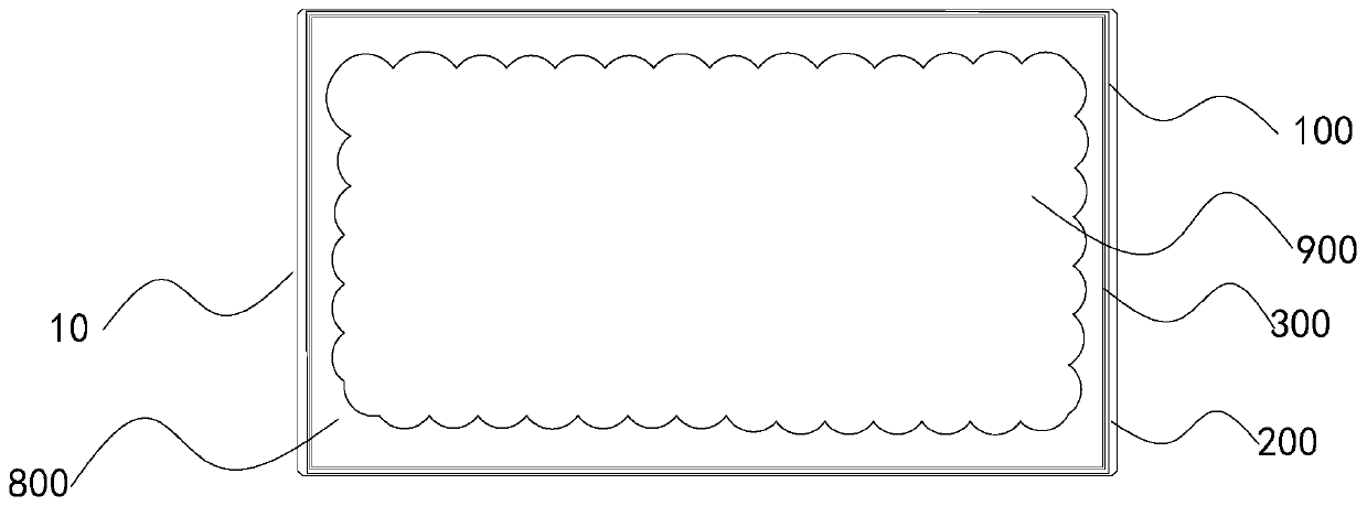
[0158] bonding the second adhesive layer of the adhesive to the display panel, and forming a sealing structure between the edge side of the display panel and the transparent protective layer, and the display panel and the transparent protective layer are adsorbed to form a bonding area and a gap area; the gap area surrounds the bonding area, and the adhesive piece surrounds the gap area. In the ...

no. 2 example

[0159] In the second embodiment, the method specifically includes the following steps:

[0160] placing the display panel on the first platform;

[0161] bonding the second adhesive layer of the adhesive member to the display panel, and placing the transparent protective layer on the display panel;

[0162] Under the action of its own gravity or external force, the transparent protective layer at least partially sags its central region toward the display panel side, and at least partially evacuates the air between the transparent protective layer and the display panel;

[0163] bonding the first adhesive layer of the adhesive member to the transparent protective layer to form a sealing structure between the edge side of the display panel and the transparent protective layer, the display panel and the transparent protective layer are adsorbed to form a bonding area and a gap area; the gap area surrounds the bonding area, and the adhesive piece surrounds the gap area.

[0164]...

no. 3 example

[0165] In the third embodiment, the method specifically includes the following steps:

[0166] placing the transparent protective layer on the first platform;

[0167] bonding the first adhesive layer of the adhesive member to the transparent protective layer, and placing the display panel on the transparent protective layer;

[0168] Under the action of its own gravity or external force, the central region of the display panel is at least partially sunken toward the side of the transparent protective layer, and the air between the transparent protective layer and the display panel is at least partially evacuated;

[0169] The second adhesive layer of the adhesive is bonded to the display panel to form a sealing structure between the edge side of the display panel and the transparent protective layer, and the display panel and the transparent protective layer are adsorbed to form a bonding area and A gap area; the gap area surrounds the bonding area, and the adhesive piece su...


PUM

PropertyMeasurementUnit
thicknessaaaaaaaaaa
heightaaaaaaaaaa

Abstract

The invention discloses a display assembly, display equipment and an assembly method of the display assembly. The display assembly comprises a display panel, a transparent protection layer and a binding piece, wherein the binding piece is arranged in a way encircling an edge of the display panel, one surface of the binding piece is fixedly connected with the display panel, the other surface of thebinding piece is fixedly connected with the transparent protection layer, the display panel and the transparent protection layer form a binding region and a gap region, the gap region encircles the binding region, and the binding piece encircles the gap region. By the display assembly, the problems of screen breakage, spray, scratch by grinding and optical leakage of the display assembly of the display equipment are effectively solved, the display effect is improved, and the production cost of the display equipment is reduced.

Description

technical field [0001] The present invention relates to the field of display devices, more specifically, a display component, a display device and an assembly method thereof. Background technique [0002] Existing display devices are widely used in people's lives. After a long period of observation, the inventor found that quality problems such as screen breakage, water mist, abrasion, and light leakage often occur in the process of use, transportation, handling, and movement of the display device. Especially for large-size display devices, quality problems such as broken screens, water mist, abrasions, and light leakage are more obvious. The display panel is one of the key components of the display device, and its cost generally accounts for about 30% or even higher of the entire display device. The unit price of each display panel ranges from hundreds of yuan to tens of thousands of yuan. For the manufacturers and sellers of display equipment, if the above-mentioned qual...

Claims


Application Information

Patent Timeline
Patent Type & Authority Applications(China)
IPC IPC(8): G02F1/1339G02F1/1333G06F3/041
CPCG02F1/1339G02F1/13338G06F3/0412G06F2203/04103G06F3/041G06F1/1601G02F1/133331G02F1/133354G02F1/133528G02F1/1336G02B1/14G02B5/3025
Inventor 周科松
Owner GUANGZHOU SHIYUAN ELECTRONICS CO LTD
Why Eureka
Try Eureka