Casting device and method for precoated sand stacking type product

A pouring method and technology of coated sand, applied in the directions of mold, core, mold composition, etc., can solve the problems of the large number of runners, the spheroidization decline of ductile iron products, and the interruption of molten iron, so as to achieve a reasonable pouring process. , Avoid cold insulation defects and improve product efficiency

Active Publication Date: 2019-10-18
西安合力汽车配件有限公司
View PDF9 Cites 3 Cited by
  • Summary
  • Abstract
  • Description
  • Claims
  • Application Information

AI Technical Summary

Problems solved by technology

At this time, due to the large number of runners, the flow rate into each runner is uncertain, so that the product process yield cannot be improved
[0005] 2) The number of pouring layers is large, and the order in which the poured molten iron enters the casting cavity is not filled layer by layer
In this way, the flow rate and speed of molten iron entering the casting cavity are uncontrollable, and some casting cavity will enter part of the molten iron first, and the subsequent molten iron cannot be replenished in time, causing the molten iron to stop flowing,

Method used


Image

  • Casting device and method for precoated sand stacking type product
  • Casting device and method for precoated sand stacking type product
  • Casting device and method for precoated sand stacking type product

Examples


Embodiment 1

[0055] Refer to attached Figure 3-6 As shown, a pouring device for coated sand stacked products, including:

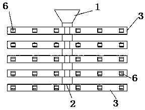
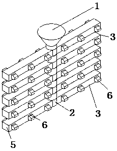
[0056] A pouring frame, which includes a sprue cup 1, a sprue 2, and a number of parallel pouring layers 3; specifically, the sprue cup 1 is arranged on the top of the pouring frame, which is a funnel-shaped structure; the bottom of the sprue cup 1 It communicates with the sprue 2;

[0057] As an improvement, in this embodiment, at least the diversion runner 4 at the bottom is included, and the diversion runner 4 forms a drainage section, and the drainage section is used to divert the casting liquid at the bottom to the upper pouring layer during pouring;

[0058] Both sides of the drainage section are respectively connected with the sprue 2 and the runner 5, the runner 5 forms the pouring layer 3, and each pouring layer 3 is provided with a number of ingates 6, and each ingate Gate 6 is connected to the casting to be poured;

[0059] In this embodiment, the height...

Embodiment 2

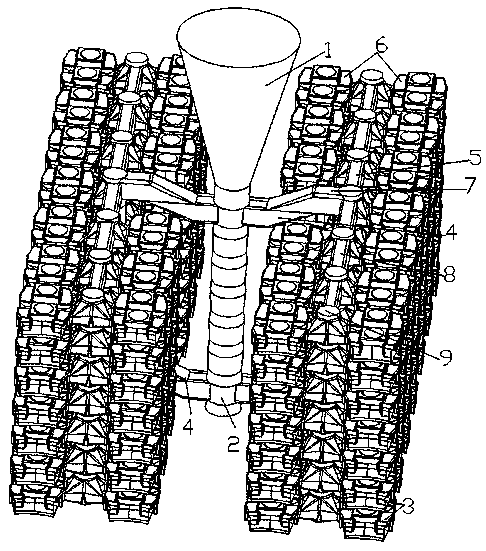
[0073] Refer to attached Figure 3-6 As shown, in this embodiment, the lower surface of the runner 5 partially overlaps with the upper surface of the runner 4 , so that the runner 5 partially overlaps the runner 4 .

[0074] Due to the partial overlap between the runner 4 and the runner 5, the molten iron can stably enter the runner 5 and the runner 4 when it flows, which reduces the risk of molten iron flow interruption and is conducive to product filling whole.

[0075] In this embodiment, the upper runner 5 and the shunt runner 4 are partially stacked, which can prevent molten iron from entering the upper runner 5 first, so that the molten iron first enters the bottom shunt runner 4 from the sprue 2 and then Enter the runner 5, and then enter the casting through the gate 6. Through such pouring, the bottom pouring form is realized, and molten iron flows from the pouring layer 3 of the next layer into the ingate 6 of the pouring layer 3 of the upper layer, and then enters ...

Embodiment 3

[0089] In this embodiment, the runner 5 at least includes a first runner 7 and a second runner 8, and the first runner 7 and the second runner 8 are respectively perpendicular to the sprue 2, And the first runner 7 is perpendicular to the second runner 8; the first runner 7 is directly arranged on the diversion runner 4, and the first runner 7 is provided with several second runners The second runner 8 is provided with the ingate 6 .

[0090] In this embodiment, the number of castings can be increased through multiple runners; compared with the prior art, when multiple pouring layers are required, the prior art can only directly connect how many runners; and this embodiment Among them, since the second runner 8 is equivalent to the direct pouring runner of the prior art, and then by adjusting the first runner, the number of runners directly connected with the sprue 2 can be reduced, so that the runner The number is adjusted by the second runner 8, and the number of the first ...


PUM

PropertyMeasurementUnit
Heightaaaaaaaaaa

Abstract

The invention discloses a casting device and method for a precoated sand stacking type product. The casting device comprises a casting frame; the casting frame comprises a sprue cup, a straight pouring gate and a plurality of parallel casting layers; the sprue cup is arranged on the top of the casting frame; the straight pouring gate communicates with the sprue cup; at least a flow dividing transverse pouring gate located on the bottommost layer is included, and the flow dividing transverse pouring gate forms a flow guiding segment; during casting, the flow guiding segment is used for guidingcasting liquid at the bottommost layer to flow to an upper casting layer; the two sides of the flow guiding segment are correspondingly connected with the straight pouring gate and the transverse pouring gate; the transverse pouring gate forms the plurality of casting layers; each casting layer is provided with a plurality of inner sprues, and each inner sprue is connected with a to-be-cast casting; and the height of the casting frame is 800-1000 mm. The casting device makes casting start from the bottommost layer, the casting efficiency is improved, meanwhile, due to the casting manner, the flowing direction of molten iron is controllable, and cold insulating defects are reduced.

Description

technical field [0001] The invention belongs to the technical field of pouring, and in particular relates to a pouring device and a pouring method for coated sand products. Background technique [0002] In the prior art, small products of coated sand generally adopt horizontal stacked pouring. Refer to attached Figure 1-2 As shown, the process method of this method is that the order in which molten iron enters the cavity is: sprue cup 1--sprue 2--runner 5 (entering at the same time, the flow rate is uncertain)--ingate 6 (simultaneously entry, indeterminate flow rate) - castings (simultaneous entry, indeterminate flow rate). [0003] After the above-mentioned existing technology adopts stacking, there are the following disadvantages due to the increase in the number of casting layers. [0004] 1) The more layers of pouring, the more runners are needed. For example, the stack height of SLDEI6-8 block produced by the company is 26 layers, and 26 runners are needed. At this ...

Claims


Application Information

Patent Timeline
IPC IPC(8): B22C9/08
CPCB22C9/082B22C9/088
Inventor 刘少利叶少腾康健张义涛杨兴顿
Owner 西安合力汽车配件有限公司
Why Eureka
Try Eureka