
Polishing machine

A grinding machine and adjusting device technology, applied in grinding machines, grinding workpiece supports, grinding/polishing equipment, etc., can solve problems such as mistakes, substandard installation accuracy of parts, complicated belt adjustment, etc., to ensure safety and ensure normal sanding effect

Active Publication Date: 2019-10-18
SHAOYANG UNIV
View PDF16 Cites 1 Cited by
  • Summary
  • Abstract
  • Description
  • Claims
  • Application Information

AI Technical Summary

Problems solved by technology

The general operation of the factory is: workers directly hold the workpiece close to the grinding wheel of the grinding machine. During the grinding process, the iron filings splash and easily touch the human skin or fall into the eyes, which poses a high safety hazard.
Over time, people are prone to fatigue, easy to cause mistakes, and cause damage to the workpiece
When it is necessary to grind a certain angle or cutting amount, the existing grinding machine needs to rely on the experience of the workers to adjust the offset and strength properly. A little carelessness will easily cause a huge error, resulting in the installation accuracy of the parts not meeting the standard or even being scrapped.
[0003] Grinding machines generally use a belt to drive the grinding wheel to rotate. The belt occupies a heavy position in power transmission. Too loose or too tight a belt will affect the transmission efficiency.
In the prior art, the adjustment of the belt is complicated, and the adjustment speed of the belt tightness is slow

Method used


Image

  • Polishing machine
  • Polishing machine
  • Polishing machine

Examples


Embodiment Construction

[0025] In order to make the object, technical solution and advantages of the present invention clearer, the present invention will be further described in detail below in conjunction with the accompanying drawings and embodiments. It should be understood that the specific embodiments described here are only used to explain the present invention, not to limit the present invention.

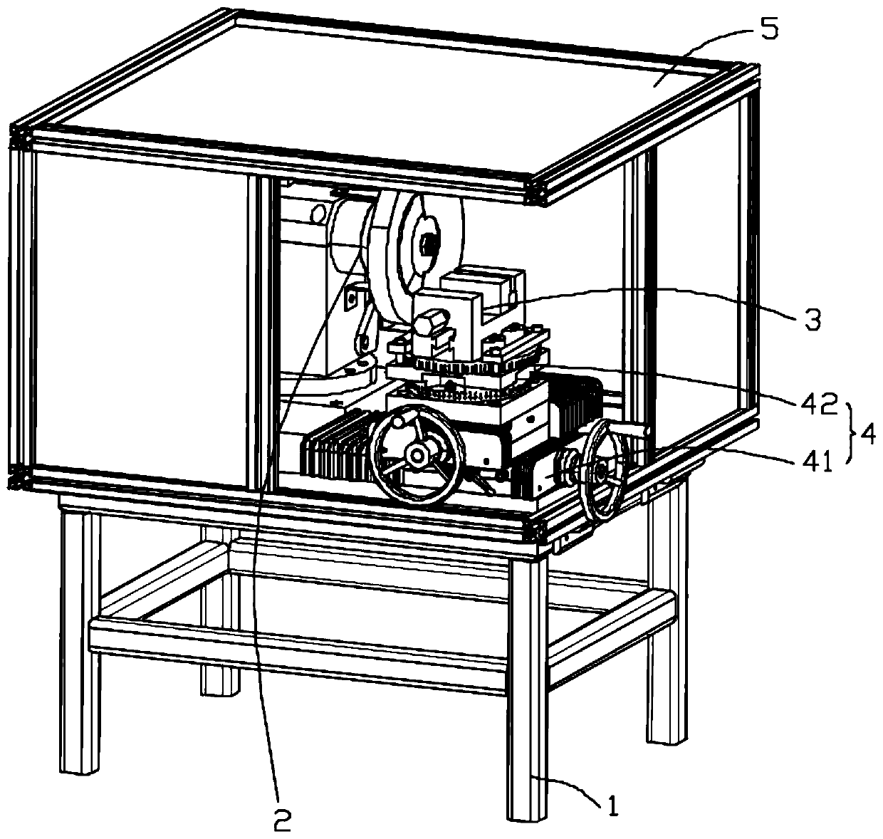
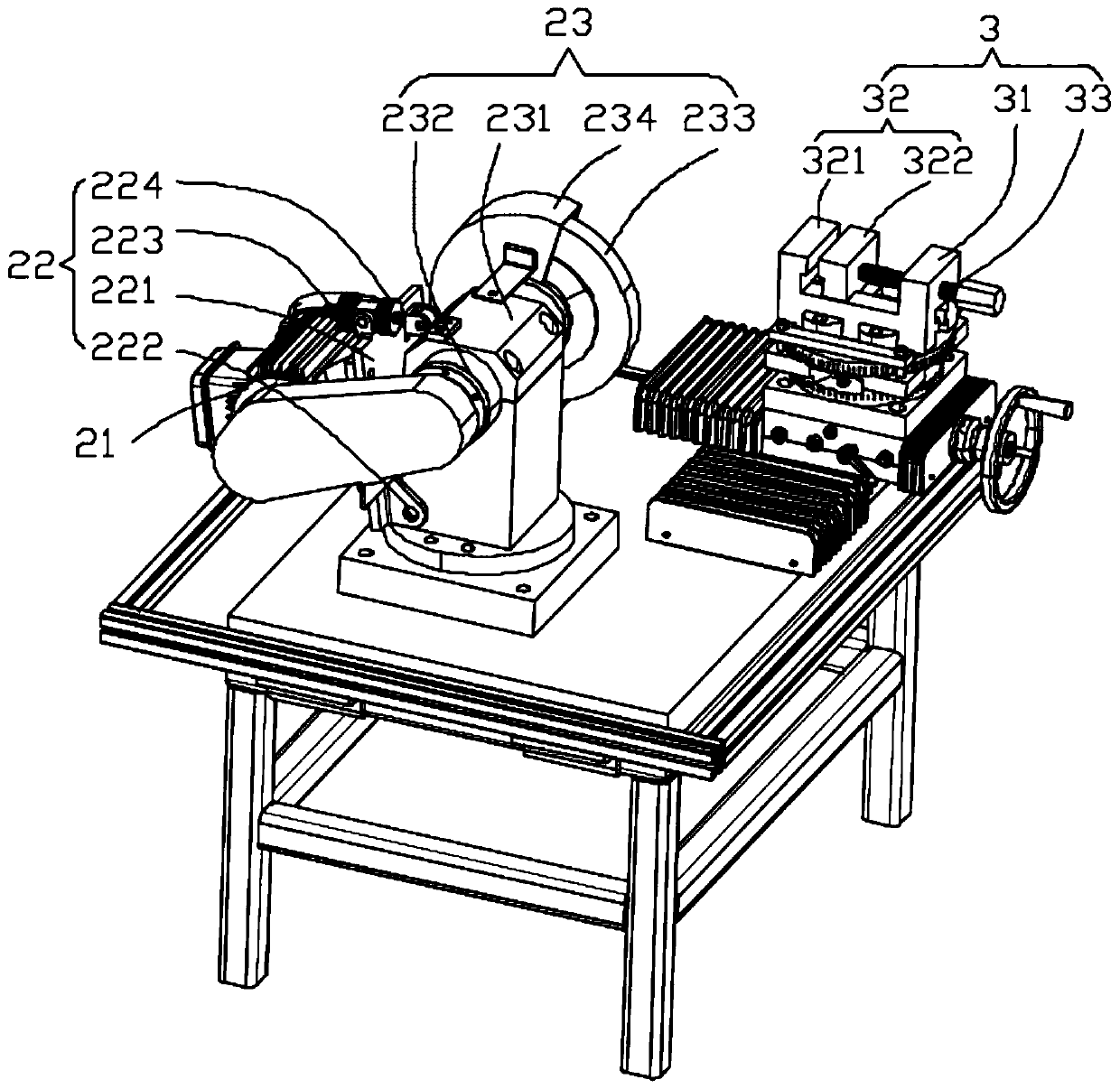
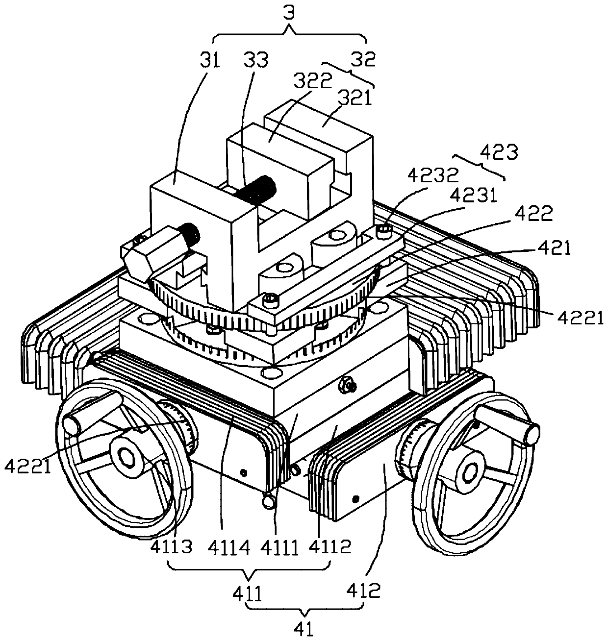
[0026] Refer to attached Figure 1-3 , a grinding machine, comprising: a base device 1, a grinding device 2, a clamp device 3, an adjustment device 4, the grinding device 2 is fixed on the upper end of the base device 1, the adjustment device 4 is fixed on the upper end of the base device 1, and the clamp device 3 is fixed At the upper end of the adjustment device 4. The adjustment device 4 includes: a direction adjustment structure 41 and an angle adjustment structure 42 , the angle adjustment structure 42 is fixed on the upper end of the direction adjustment structure 41 , and the direction adju...


PUM


Abstract

The invention provides a polishing machine. The polishing machine comprises a base device, a polishing device, a clamp device and an adjusting device, wherein the polishing device is fixed at the upper end of the base device, the adjusting device is fixed at the upper end of the base device, and the clamp device is fixed at the upper end of the adjusting device. The adjusting device comprises a direction adjusting structure and an angle adjusting structure, wherein the angle adjusting structure is fixed at the upper end of the direction adjusting structure, and the direction adjusting structure is fixed at the upper end of the base device. The angle adjusting structure comprises a main body part and a dial, wherein the main body part is fixed at the upper end of the direction adjusting structure, the dial is arranged at the upper end of the main body part, and the dial is rotationally connected with the main body part. According to the polishing machine, workpieces can be precisely polished and accurately cut through the direction adjusting structure and the angle adjusting structure, iron scraps are prevented from splashing by means of a protection hood, the grinding safety of workers is improved, the tightness of a belt is conveniently adjusted, and normal polishing of a polishing wheel is guaranteed.

Description

technical field [0001] The invention belongs to the technical field of grinding equipment, and in particular relates to a grinding machine. Background technique [0002] Existing grinders generally consist of a grinder and a fixed base, without protection devices and workpiece clamping devices. The common operation in the factory is: workers directly hold the workpiece close to the grinding wheel of the grinding machine. During the grinding process, iron filings splash and easily touch the human skin or fall into the eyes, which poses a high safety hazard. Over time, people are prone to fatigue, which can easily cause mistakes and cause damage to the workpiece. When it is necessary to grind a certain angle or cutting amount, the existing grinding machine needs to rely on the experience of the workers to adjust the offset and strength properly. A little carelessness will easily cause a huge error, resulting in the installation accuracy of parts not meeting the standard or ev...

Claims


Application Information

Patent Timeline
Patent Type & Authority Applications(China)
IPC IPC(8): B24B27/00B24B41/06B24B55/04B24B55/00
CPCB24B27/00B24B27/0092B24B41/06B24B55/00B24B55/04
Inventor 李冬英白豪李梦奇
Owner SHAOYANG UNIV
Learn More