
Rotary chuck for remedial work

A rotary chuck and operation technology, which is applied in the direction of drilling equipment, earthwork drilling, drill pipe, etc., can solve the problems that the anti-top chuck and anti-fall chuck cannot rotate with the oil pipe, and cannot meet the requirements of rotation operations, so as to achieve convenient The effect of replacement

Inactive Publication Date: 2019-10-18
西安宇星石油机械新技术开发有限公司
View PDF6 Cites 1 Cited by
  • Summary
  • Abstract
  • Description
  • Claims
  • Application Information

AI Technical Summary

Problems solved by technology

[0004] In order to solve the technical problem that the existing workover operation anti-top chuck and anti-drop chuck cannot rotate with the tubing, which can not meet the requirements of rotation operations such as make-up and breakout in the workover operation under pressure, and grinding and milling procedures in the conventional workover operation, The invention provides a workover operation rotary chuck

Method used


Image

  • Rotary chuck for remedial work
  • Rotary chuck for remedial work
  • Rotary chuck for remedial work

Examples


Embodiment Construction

[0029] The present invention will be further described below in conjunction with the accompanying drawings and specific embodiments.

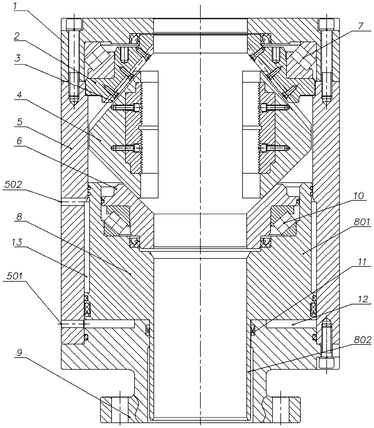
[0030] refer to figure 1 , including an intermediate casing formed by connecting an upper flange 1, an intermediate casing 5 and a lower flange 9 in series.

[0031] The casing is provided with an upper rotating body 2 , two dovetail-shaped guide keys 3 , a slip body assembly 4 , a lower rotating body 6 and a piston 8 in sequence from top to bottom. The inner holes of the lower end of the upper rotating body 2 and the upper end of the lower rotating body 6 are tapered holes; both ends of the slip body assembly 4 are tapered surfaces.

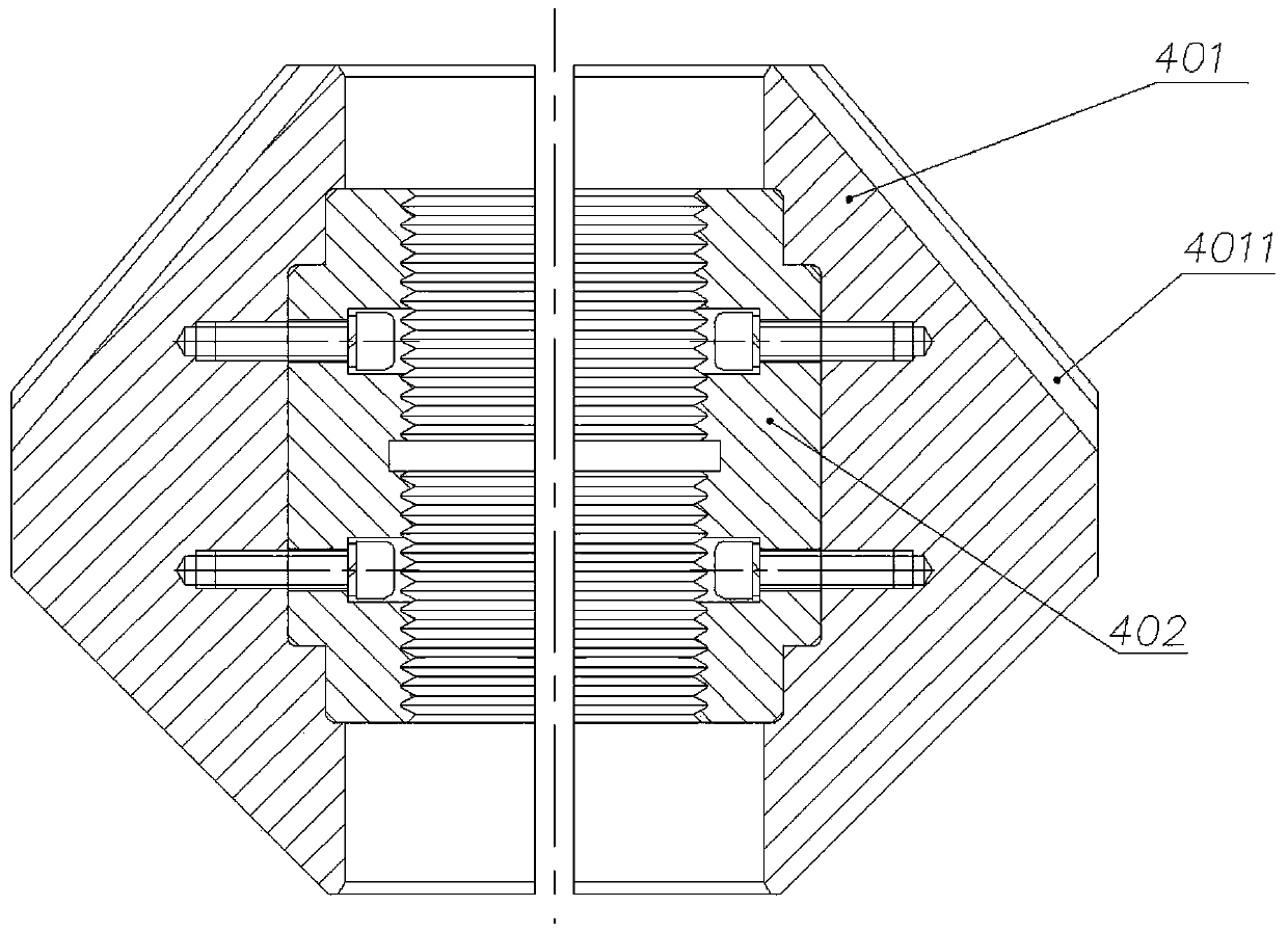
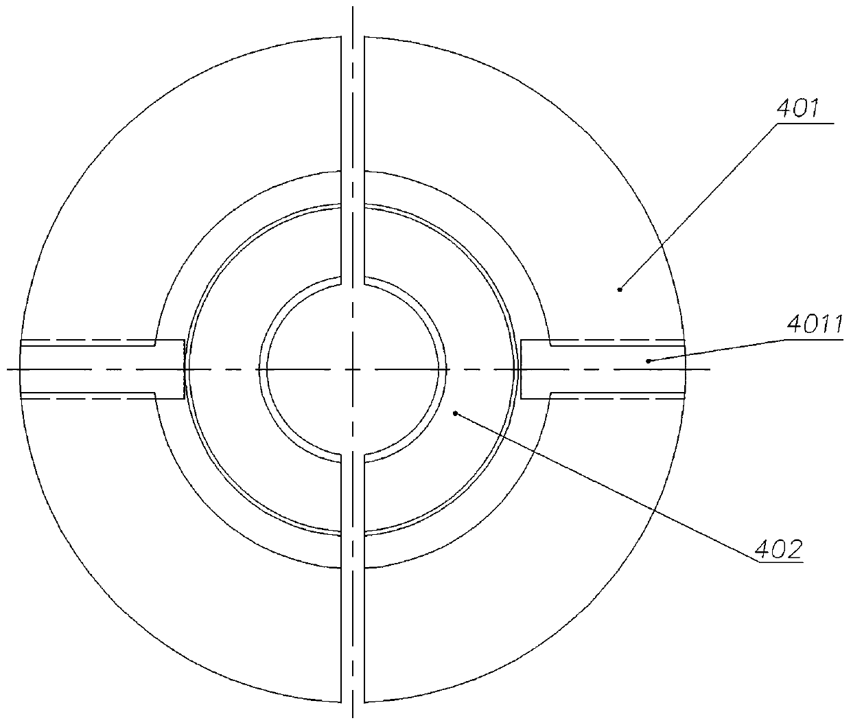
[0032] refer to figure 2 and image 3 , the slip body assembly 4 is a split type, including two slip bodies 401 and slips 402 respectively fixed in each slip body 401; each slip body 401 is provided with a dovetail-shaped guide key on the conical surface 3 fit the dovetail groove 4011.

[0033] refer to fi...


PUM


Abstract

The invention relates to a chuck for remedial work, in particular to a rotary chuck for remedial work, and the rotary chuck solves the technical problems that an existing remedial work anti-jacking chuck and an existing remedial work anti-dropping chuck cannot meet rotary operation requirements of screw-off on under-pressure remedial work, a conventional remedial work grinding and milling process,and the like while not rotating along with an oil tube or a down-hole tool cannot rotate along with the oil tube. According to the technical scheme adopted by the invention, the rotary chuck for remedial work comprises a middle through housing which is formed by connecting an upper flange, a middle housing and a lower flange in series, wherein an upper rotary body, at least two dovetail-shaped guide keys, a blocking tile body assembly, a lower rotary body and a piston are sequentially arranged in the housing from top to bottom; the upper rotary body is supported on the upper flange through abearing; the dovetail-shaped guide keys are fixedly arranged on the inner conical surface of the upper rotary body; the blocking tile body assembly is in sliding connection to the dovetail-shaped guide keys; the blocking tile body assembly is placed on the lower rotary body; and the lower rotary body is supported on the piston through a bearing.

Description

technical field [0001] The invention relates to a well workover operation chuck, in particular to a well workover operation rotary chuck. Background technique [0002] In the workover operation, the anti-top chuck and the anti-drop chuck are respectively fixed on the upper and lower parts of the floating bracket, and the floating bracket is connected with the lifting cylinder, which drives the floating bracket and the anti-top The chuck and the anti-drop chuck move up and down to realize the lifting or lowering of the tubing or downhole tool. Among them, the anti-top chuck is used to clamp the tubing or downhole tool to prevent it from being ejected, and the anti-drop chuck is used to prevent the tubing from falling out. Or downhole tool tubing falls into the well. [0003] Since the existing anti-top chucks and anti-drop chucks are fixed on the floating bracket and cannot rotate with the tubing, it cannot meet the requirements of rotary operations such as making up and bre...

Claims


Application Information

Patent Timeline
Patent Type & Authority Applications(China)
IPC IPC(8): E21B19/10
CPCE21B19/10
Inventor 雷宽成李继荣邢建峰宋喆王利娜王静郭超赵小平
Owner 西安宇星石油机械新技术开发有限公司
Learn More