Drive structure, main mechanical arm and auxiliary mechanical arm

A driving structure and manipulator technology, applied in the field of manipulators, can solve problems such as limited, unfavorable clamping workpiece adjustment and calibration, and the working arm cannot reach the installation position very accurately, so as to reduce the swing speed, facilitate adjustment and calibration, and adjust the accuracy Good results

Pending Publication Date: 2019-10-18
江西鑫通机械制造有限公司
View PDF0 Cites 0 Cited by
  • Summary
  • Abstract
  • Description
  • Claims
  • Application Information

AI Technical Summary

Problems solved by technology

[0003] The mechanical arm on the arch trolley is mostly directly driven by an oil cylinder or in the form of an oil cylinder + four-link drive. However, when the above two structures are in the attitude calibration position, due to the limitation of the adjustment stroke of the hydraulic valve and the oil cylinder, the hydraulic pressure The cylinder speed is as slow as 2-3 mm / s is the limit. Under the premise of this speed, the linear speed of the swing end of the rocker arm will also reach 40-80 mm / s, which is very unfavorable for the adjustment and calibration of the clamped workpiece, that is, the working arm Can not be very accurate to reach the installation position

Method used


Image

  • Drive structure, main mechanical arm and auxiliary mechanical arm
  • Drive structure, main mechanical arm and auxiliary mechanical arm
  • Drive structure, main mechanical arm and auxiliary mechanical arm

Examples


Embodiment 1

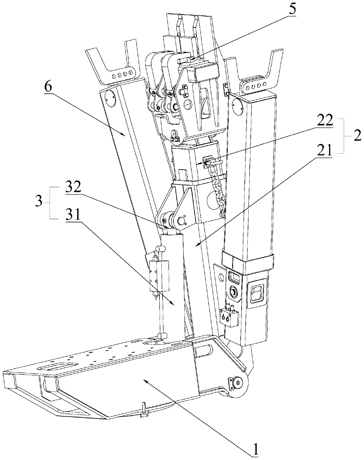
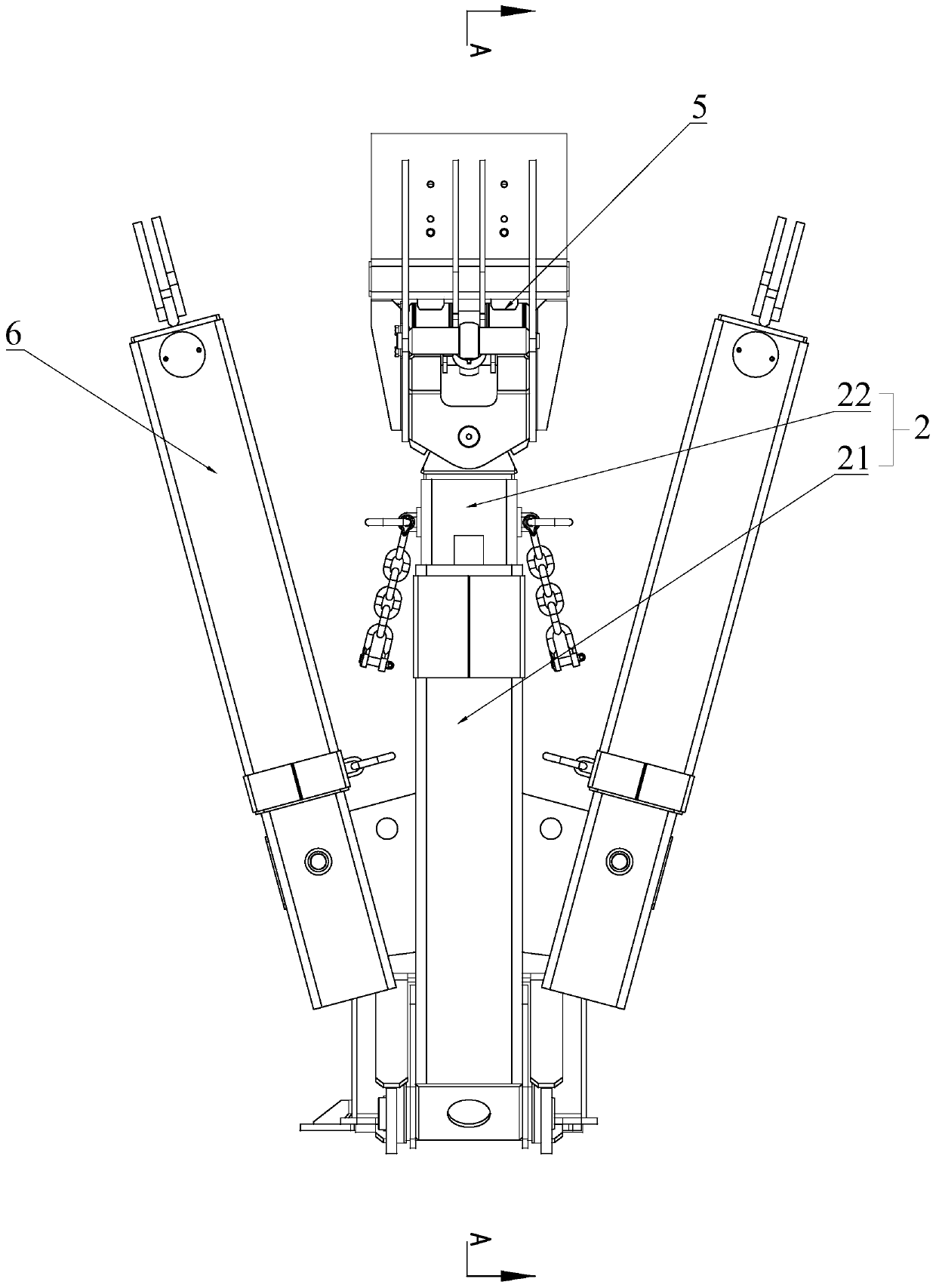
[0025] See figure 1 , figure 2 , image 3 As shown, the driving structure of the present invention includes a base 1 and a manipulator 2 hinged on the base 1. The manipulator 2 is hinged with a first driving member 3 that drives the manipulator 2 to rotate, and the first driving member 3 is connected with The second driving part 4 that changes the position of the first driving part 3 is arranged on the base 1. The position of the first driving member 3 is adjusted by the second driving member 4. When the manipulator 2 is rotated from the first position to the second position, the second driving member 4 of the front section adjusts the position of the first driving member 3 along the rotation direction of the manipulator 2, That is to say, the swing speed can be increased to achieve rapid swing. When the manipulator 2 quickly swings to the second position, the second drive member 4 adjusts the position of the first drive member 3, and the first drive member 3 does not operate t...

Embodiment 2

[0029] See figure 1 , figure 2 , image 3 As shown, the driving structure of the present invention includes a base 1 and a manipulator 2 hinged on the base 1. The manipulator 2 is hinged with a first driving member 3 that drives the manipulator 2 to rotate, and the first driving member 3 is connected with The second driving member 4 that changes the position of the first driving member 3.

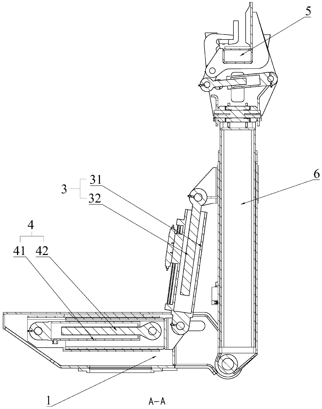
[0030] The first driving member 3 includes a first cylinder 31 and a first telescopic rod 32 slidably connected in the first cylinder 31, and the first telescopic rod 32 is hinged to the manipulator 2. It can be adjusted effectively with the manipulator 2. The second driving member 4 is arranged on the base 1, and the second driving member 4 includes a second cylinder 41 and a second telescopic rod slidably connected in the second cylinder 41 42. The second cylinder 41 is fixedly connected to the base 1, and the end of the second telescopic rod 42 is connected to the first driving member 3. ...

Embodiment 3

[0033] The basic structure is the same as the second embodiment of the working arm structure, except that the second telescopic rod 42 is fixedly connected to the first cylinder 31. The fixed connection refers to the structure that can connect the second telescopic rod 42 and the first cylinder 31 fixedly, that is, the fixed connection is realized when the first driving member 3 and the second driving member 4 are running for some time, that is, the first driving The angle between the part 3 and the second driving part 4 is constant. When the manipulator is adjusted to operate, the first driving part 3 and the second driving part 4 will inevitably run at the same time. The first driving part is adjusted along the rotation direction of the manipulator 2 through the second driving part 4 The position of the part 3 can speed up the swing speed and achieve rapid swing, or adjust the position of the first driving part 3 in the opposite direction of the rotation of the manipulator 2 t...


PUM


Abstract

The invention discloses a drive structure, a main mechanical arm and an auxiliary mechanical arm. The drive structure comprises a base and a mechanical arm hinged to the base. A first drive piece driving the mechanical arm to rotate is hinged to the mechanical arm and is connected with a second drive piece changing the position of the first drive piece. The second drive piece is arranged on the base and adjusts the position of the first drive piece. When the mechanical arm rotates to the second position from the first position, the part, at a front section part, of the second drive piece adjusts the position of the first drive piece in the mechanical arm rotation direction so that the swinging speed can be increased, and rapid swinging is achieved. When the mechanical arm rapidly swings tothe second position, the second drive piece adjusts the position of the first drive piece, the first drive piece does not run, small-angle fine adjustment of the position of the first drive piece isachieved, fine adjustment of the mechanical arm through the first drive piece is achieved, and the swinging end of the mechanical arm can swing 10-15 mm/s.

Description

Technical field [0001] The present invention relates to a mechanical arm, more specifically to a driving structure and a main manipulator and an auxiliary manipulator. Background technique [0002] In the existing tunnel excavation, it is necessary to install multiple steel arches along the length of the tunnel to prevent the tunnel from collapsing. In order to meet the requirements, the length of each steel arch is correspondingly larger. Therefore, usually during the construction process, The steel arch frame is divided into multiple arch frame sections, and the arch frame trolley clamps the arch frame section to the installation position through the working arm. [0003] Most of the manipulator arms on the arch trolley are directly driven by an oil cylinder or driven by an oil cylinder + four connecting rods. However, when the above two structures are in the attitude calibration position, they are limited by the adjustment stroke of the hydraulic valve and the oil cylinder. The...

Claims


Application Information

Patent Timeline
Patent Type & Authority Applications(China)
IPC IPC(8): E21D11/40E21D11/18B25J9/10B25J18/00
CPCE21D11/40E21D11/18B25J9/10B25J18/00
Inventor 邹海波刘建春张镇
Owner 江西鑫通机械制造有限公司
Why Eureka
Try Eureka