
A Cantilever Laser Optical Path Calibration Device

An optical path calibration, cantilever technology, applied in laser welding equipment, metal processing equipment, welding equipment and other directions, to achieve the effect of convenient adjustment, convenient horizontal and vertical adjustment, coherent and efficient way

Active Publication Date: 2021-07-20
ANHUI CHUNGU 3D PRINTING INTELLIGENT EQUIP IND TECH RES INST CO LTD
View PDF7 Cites 0 Cited by
  • Summary
  • Abstract
  • Description
  • Claims
  • Application Information

AI Technical Summary

Problems solved by technology

[0005] The purpose of the present invention is to provide a cantilever type laser optical path calibration device to solve the problems of different parts of the conventional calibration equipment in the prior art proposed in the above-mentioned background technology

Method used


Image

  • A Cantilever Laser Optical Path Calibration Device
  • A Cantilever Laser Optical Path Calibration Device
  • A Cantilever Laser Optical Path Calibration Device

Examples


Embodiment Construction

[0027] The following will clearly and completely describe the technical solutions in the embodiments of the present invention with reference to the accompanying drawings in the embodiments of the present invention. Obviously, the described embodiments are only some, not all, embodiments of the present invention. The specific embodiments described here are only used to explain the present invention, not to limit the present invention. Based on the embodiments of the present invention, all other embodiments obtained by persons of ordinary skill in the art without making creative efforts belong to the protection scope of the present invention.

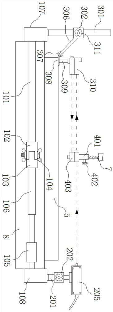
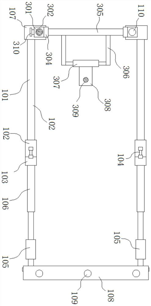
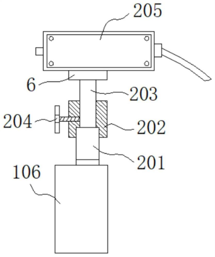
[0028] The present invention provides such Figure 1-6 A cantilever type laser optical path calibration device shown includes a connecting rod 101, a butterfly bolt 104, a connecting pipe 106, a fixing plate 108, an operating table 5 and a frame 8, and one end of the connecting rod 101 is fixedly connected with a fixing seat 107, The oth...


PUM


Abstract

The invention discloses a cantilever type laser optical path calibration device, which comprises a connecting rod, a butterfly bolt, a connecting pipe, a fixing plate, an operating table and a frame, one end of the connecting rod is fixedly connected with a fixing seat, and the connecting rod The other end is fixedly connected with a first connector, and an electric push rod is fixedly installed on the fixed plate. The present invention measures the technical parameters of the operating table of the equipment and the technical parameters of the drill bit simultaneously by setting an adjustable laser, the first receiver and the second receiver, and the optical path of the laser first passes through the second receiver to the first receiver , under the refraction of the triangular prism inside the first receiver, the laser light path is reflected and then transmitted to the second receiver, so as to facilitate the adjustment and calibration of the staff, and the way of laser calibration and adjustment is coherent and efficient; The horizontal and vertical adjustment of the receiver is convenient, and the calibration and adjustment of the cantilever laser calibration device is convenient.

Description

technical field [0001] The invention belongs to the technical field of laser calibration equipment, and in particular relates to a cantilever type laser optical path calibration device. Background technique [0002] Lasers have many characteristics. First, lasers are monochromatic, or single-frequency. There are some lasers that can generate laser light of different frequencies at the same time, but these laser lights are isolated from each other and used separately. Second, laser light is coherent light. The characteristic of coherent light is that all its light waves are synchronized, and the whole beam of light is like a "wave train". Again, the laser is highly concentrated, that is to say, it takes a long distance to disperse or converge. Laser is widely used, including laser marking, laser welding, laser cutting, optical fiber communication, laser ranging, laser radar, laser weapons, laser discs, laser vision correction, laser beauty, laser scanning, laser mosquito k...

Claims


Application Information

Patent Timeline
Patent Type & Authority Patents(China)
IPC IPC(8): B23K26/042
CPCB23K26/042
Inventor 艾晓蕾黄仲佳周晓宏罗贤国张勇孙文明赵薇郑兰斌吴志华王心生杨军李思文宗泽周翔吕晨
Owner ANHUI CHUNGU 3D PRINTING INTELLIGENT EQUIP IND TECH RES INST CO LTD
Learn More