Self-driving speed sensor of rotating cylindrical turbo-drill based on friction nanometer
A speed sensor and turbo drill technology, which is applied to friction generators, equipment with special mechanical means, and devices using electric/magnetic methods, etc., can solve problems such as unfavorable turbo drill speed measurement for a long time.
- Summary
- Abstract
- Description
- Claims
- Application Information
AI Technical Summary
Problems solved by technology
Method used
Image

Examples
Embodiment Construction
[0017] In order to make the purpose, technical solution and advantages of the present invention clearer, the embodiments of the present invention will be further described below in conjunction with the accompanying drawings.
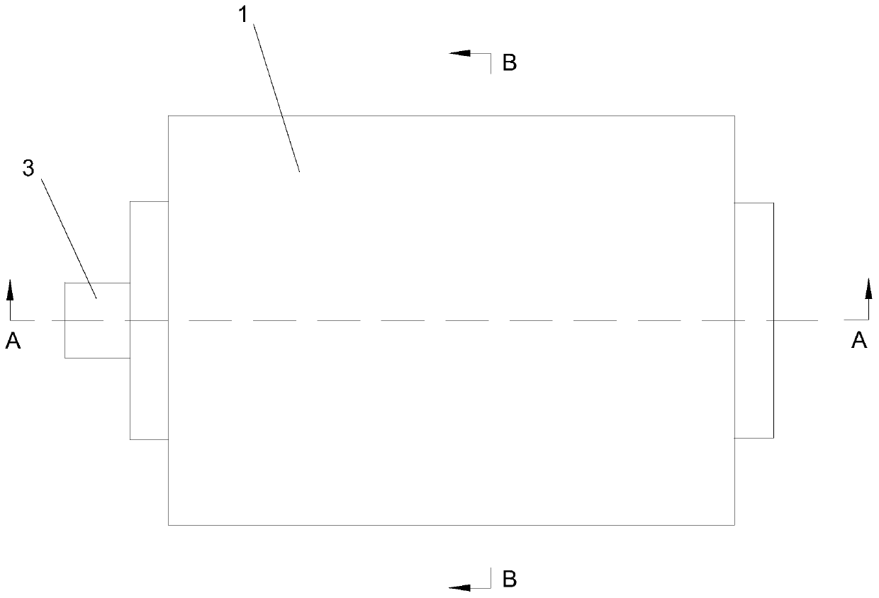
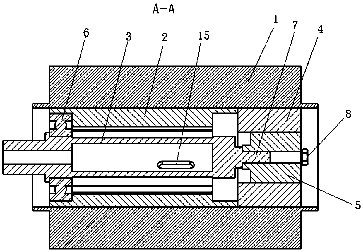
[0018] Please refer to Figure 1~3 , The embodiment of the present invention provides a self-driving rotational speed sensor of a rotary cylinder turbodrill based on friction nanometer, including a casing 1, a cylinder body 2, a drive shaft 3 and a circuit board.
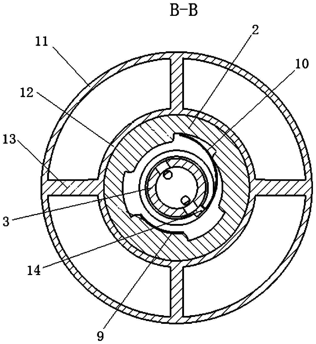
[0019] Please refer to image 3 , the shell 1 includes an outer cylinder 11 and an inner cylinder 12, the inner cylinder 12 is placed inside the outer cylinder 11, and the two are coaxial, and the outer cylinder 11 and the inner cylinder 12 are passed through a plurality of The ribs 13 are connected, and the number of the ribs 13 in this embodiment is four, and the four ribs 13 are evenly arranged around the inner cylinder 12, and the upper end of the inner cylinder 12 is higher than the uppe...
PUM
 Abstract
Description
Claims
Application Information