Motor temperature protection control system and method for high-pressure water injection pump
A technology for motor temperature and protection control, applied in emergency protection circuit devices, electrical components, etc., can solve the problems of motor insulation damage, temperature rise, motor burnout, etc. Effect
- Summary
- Abstract
- Description
- Claims
- Application Information
AI Technical Summary
Problems solved by technology
Method used
Image
Examples
specific Embodiment approach
[0033] It should be noted that the structures, proportions, sizes, etc. shown in this specification are only used to cooperate with the content disclosed in the specification for the understanding and reading of those familiar with this technology, and are not used to limit the conditions for the implementation of the present invention , any modification of structure, change of proportional relationship or adjustment of size shall still fall within the scope covered by the technical content disclosed in the present invention without affecting the effect and purpose of the present invention. .
[0034] At the same time, terms such as "upper", "lower", "left", "right", "middle" and "one" quoted in this specification are only for the convenience of description and are not used to limit this specification. The practicable scope of the invention and the change or adjustment of its relative relationship shall also be regarded as the practicable scope of the present invention without...
Embodiment 1
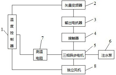
[0036] Such as figure 1 As shown, the present invention discloses a motor temperature protection and control system for a high-pressure water injection pump, including a temperature controller 1, a vector frequency converter 2, an output reactor 3, a contactor 4, a three-phase asynchronous motor 5, a water injection pump 6, a measuring temperature resistance 7 and independent fan 8, the temperature controller 1 is electrically connected to the vector frequency converter 2, the temperature measuring resistance 7 and the independent fan 8, the vector frequency converter 2 is electrically connected to the output reactor 3, and the output reactor 3 is connected to the The contactor 4 is electrically connected to the three-phase asynchronous motor 5, the three-phase asynchronous motor 5 is electrically connected to the water injection pump 6, the temperature measuring resistor 7 is fixed on the three-phase asynchronous motor 5, and the independent fan 8 is set on three phase asynch...
Embodiment 2
[0040] Preferably, the independent fan 8 is not coaxial with the three-phase asynchronous motor 5 and is an independent fan, and the three-phase asynchronous motor 5 has its own coaxial fan.
[0041]Preferably, the coaxial fan 8 carried by the independent fan 8 and the three-phase asynchronous motor 5 is arranged on the same side of the three-phase asynchronous motor 5, wherein the clip between the independent fan 8 and the coaxial fan carried by the three-phase asynchronous motor 5 The angle is less than 10°.
[0042] The shaft of the independent fan 8 is not coaxial with the shaft of the three-phase asynchronous motor 5, so the speed of the independent fan 8 is not changed by the change of the speed of the three-phase asynchronous motor 5, and the power supply of the independent fan 8 is controlled by the temperature controller 1 , can control the start and stop of the independent fan 8 and the speed of the rotating speed.
[0043] The two fans are arranged on the same side...
PUM
 Abstract
Description
Claims
Application Information
 - R&D
- Intellectual Property
- Life Sciences
- Materials
- Tech Scout
- Unparalleled Data Quality
- Higher Quality Content
- 60% Fewer Hallucinations
Browse by: Latest US Patents, China's latest patents, Technical Efficacy Thesaurus, Application Domain, Technology Topic, Popular Technical Reports.
© 2025 PatSnap. All rights reserved.Legal|Privacy policy|Modern Slavery Act Transparency Statement|Sitemap|About US| Contact US: help@patsnap.com


