
Null broadening method for controlling sidelobe based on sparsity constraint

A sparse constraint and sidelobe technology, applied in the field of radar, can solve the problems of shallow nulling depth, fluctuation of interference direction, and difficulty in controlling the loading, and achieve the effect of good nulling depth, robust beamforming, and low sidelobe performance.

Active Publication Date: 2019-10-18
XIDIAN UNIV
View PDF4 Cites 0 Cited by
  • Summary
  • Abstract
  • Description
  • Claims
  • Application Information

AI Technical Summary

Problems solved by technology

Among them, the diagonal loading algorithm will make the zero-sink of the pattern shallower and the loading amount is difficult to control, the linear constraint method will consume too many degrees of freedom of the array, the beamforming method based on the feature space is sensitive to the dimension of the signal subspace, and the covariance-based Robust beamforming algorithms for matrix reconstruction and steering vector estimation have good robustness to steering vector mismatches, but shallow null-trap depth
For the fluctuation of the interference direction caused by the vibration of the antenna platform or the fast movement of the interference, there is currently a CMT (covariance matrix weighted) algorithm, but the CMT algorithm will lead to a shallower null depth while widening the null.

Method used


Image

  • Null broadening method for controlling sidelobe based on sparsity constraint
  • Null broadening method for controlling sidelobe based on sparsity constraint
  • Null broadening method for controlling sidelobe based on sparsity constraint

Examples


Embodiment 1

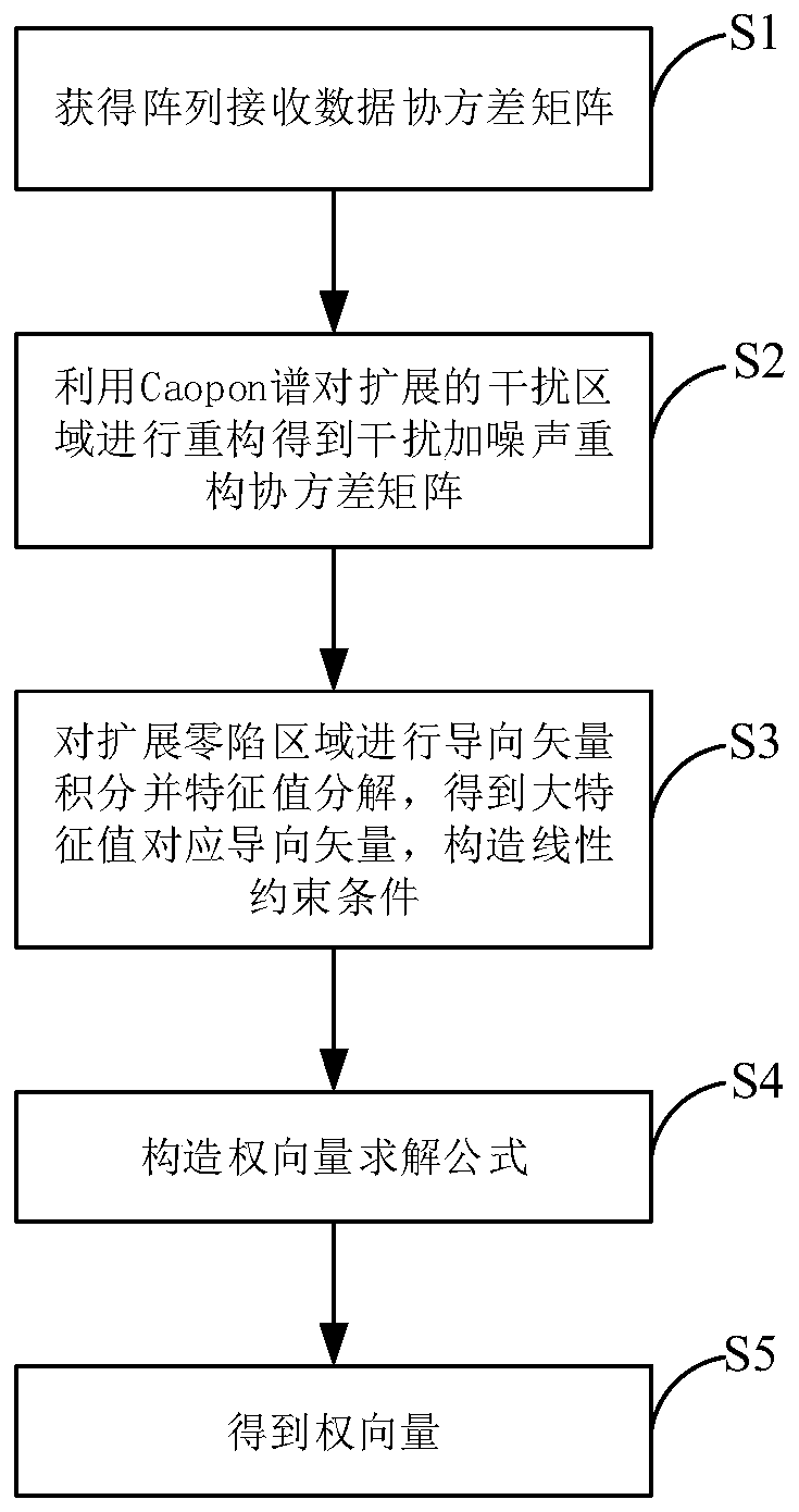
[0052] See figure 1 , figure 1It is a flow chart of a method for nulling widening of sidelobes based on sparse constraints to control side lobes provided by an embodiment of the present invention. As shown in the figure, a method for nulling widening of sidelobes based on sparse constraints to control side lobes in this embodiment includes:

[0053] S1: Obtain the received data covariance matrix of the antenna array

[0054] S2: Using the Capon power spectrum (traditional beamforming power spectrum) to analyze the received data covariance matrix The extended interference signal area is reconstructed, and the interference plus noise reconstruction covariance matrix is ​​obtained

[0055] Specifically, the interference plus noise reconstruction covariance matrix for,

[0056]

[0057] S3: For the received data covariance matrix The extended null region of the steering vector is integrated to obtain the correlation matrix of the steering vector and the correlatio...

Embodiment 2

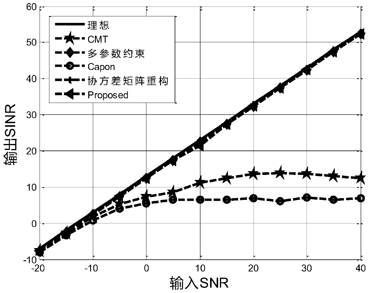
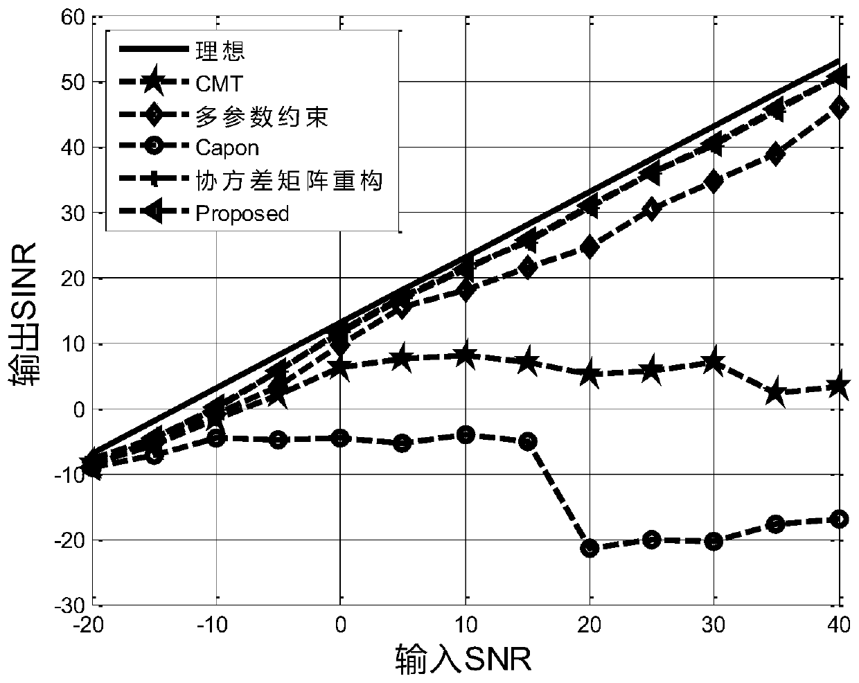
[0079] This embodiment is a further illustration of the nulling widening method based on sparsity constraints to control side lobes in the first embodiment through simulation experiments. In the simulation experiment process of this embodiment, the antenna array structure adopts a uniform linear array, the number of array elements N is 20, the spacing d between array elements is λ2, the interference directions are -30° and 40°, and the interference-to-noise ratio is 30dB, ideal The target direction is 0°, the range of SNR value is [-20:40], and the interval is 5dB.

[0080] In the experiment in which the simulated output SINR changes with the input SNR in this embodiment, the number of snapshots L is 200, and the received data covariance matrix of the array is estimated as follows:

[0081]

[0082] Among them, N represents the number of array elements, and L represents the number of snapshots.

[0083] During the simulation experiment of this embodiment, compared algorith...


PUM


Abstract

The invention relates to a null broadening method for controlling sidelobe based on a sparsity constraint, mainly directed to desired signal mismatch and interference disturbance. The null broadeningmethod comprises steps of acquiring a covariance matrix of data received by an antenna array, extending and reconstructing an interference interval known in advance by using a Capon spectrum to obtaina covariance matrix of interference plus noise; obtaining a covariance matrix of interference by conducting steering vector integral on the extended interference interval; obtaining feature vectors corresponding to large feature values by a feature space method to construct a linear constraint condition; constructing a weight vector solution formula to solve the weight vector. The method of the invention has good robustness to the desired signal mismatch and achieves null broadening, and has better null depth and lower sidelobe.

Description

technical field [0001] The invention belongs to the technical field of radar, and in particular relates to a zero trap widening method for controlling side lobes based on sparse constraints. Background technique [0002] Array signal processing technology has been widely used in many fields such as radar and communication. Its biggest advantage is that it can perform beamforming in the direction of interest to increase the energy of the signal, and form a gain null in the interference direction. Traditional adaptive beamforming algorithms are mostly proposed for ideal conditions. However, the actual environment is very complex and there are various errors, especially when the interference direction shakes and the beam pointing deviates from the desired signal direction. The forming algorithm not only cannot effectively suppress the interference, but also produces nulls in the direction of the desired signal, which seriously reduces the output SINR. [0003] Aiming at the pr...

Claims


Application Information

Patent Timeline
Patent Type & Authority Applications(China)
IPC IPC(8): G01S7/36
CPCG01S7/36
Inventor 王彤吴佳丽李娜王美凤刘程
Owner XIDIAN UNIV
Learn More