
Power grid structure planning method

A grid grid and planning technology, applied in logic circuits, electrical components, pulse technology, etc., can solve problems such as output uncertainty and load fluctuation, backward grid structure layout, and inability to adapt.

Pending Publication Date: 2019-10-18
CHANGJI POWER SUPPLY COMPANY STATE GRID XINJIANGELECTRIC POWER +3
View PDF2 Cites 2 Cited by
  • Summary
  • Abstract
  • Description
  • Claims
  • Application Information

AI Technical Summary

Problems solved by technology

Considering the uncertain factors in the power grid containing distributed new energy sources, such as the uncertainty of the output of distributed new energy sources and the fluctuation of loads, the layout of the grid structure is backward, and the design is unreasonable. In addition, the traditional based on relative Stable grid planning of large power grids cannot meet the requirements of large-scale access to uncertain distributed new energy sources
Due to the fluctuation of load, coupled with the instability of power output of some distributed power sources, such as intermittent power sources such as wind turbines and photovoltaic power sources, new problems have been brought to the planning of power distribution systems. Frame planning is no longer suitable

Method used


Image

  • Power grid structure planning method
  • Power grid structure planning method
  • Power grid structure planning method

Examples


Embodiment Construction

[0077] The present invention will be further described below in conjunction with the accompanying drawings and specific embodiments.

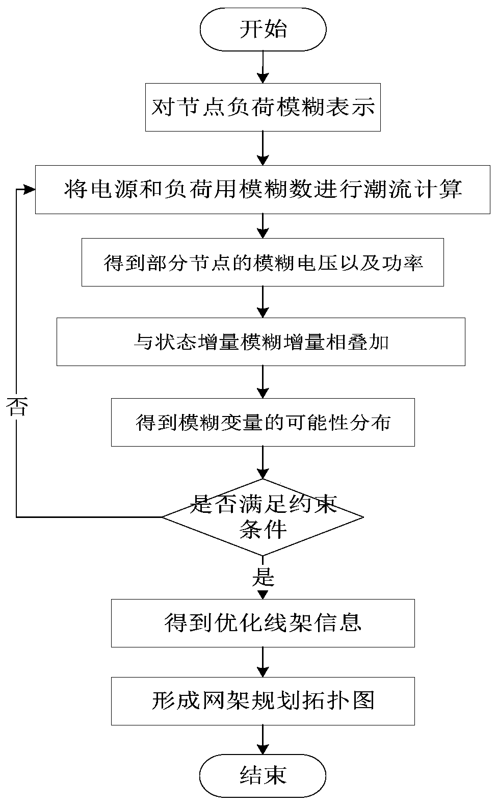
[0078] Such as figure 1 As shown, the specific steps of the grid optimization method of the present invention are as follows:

[0079] (1) Express the node load with a fuzzy method;

[0080] (2) Use the fuzzy method to express the power grid load, and substitute it into the conventional power flow calculation;

[0081] (3) Superimpose the conventional power flow calculation with the state increment fuzzy increment. The obtained membership functions of each state variable and output variable can obtain the possibility distribution of each state variable, namely voltage, phase angle, power, etc.;

[0082] (4) Determine the constraints of grid planning, active and reactive economic constraints, economic constraints, and maximum load constraints. If the constraints are not met, grid planning will be re-executed;

[0083] (5) Obtain the optimize...


PUM


Abstract

The invention discloses a power grid structure planning method, which comprises the following steps of: representing a power grid load by using a fuzzy method, calculating a triangular membership function, and substituting the solved triangular membership function into a power flow calculation formula to obtain possibility distribution of power grid fuzzy power flow; then superposing the conventional load flow calculation and the state increment fuzzy increment, solving functions of each state variable and an output variable, and obtaining possibility distribution of state variables such as power, voltage, current, phase angle and the like; and then determining constraint conditions, active and reactive economic constraints, economic constraints and maximum load constraints of grid planning, and carrying out grid planning by taking minimum investment construction cost, minimum network loss and maximum distributed power supply capacity of the to-be-accessed network as targets.

Description

technical field [0001] The invention relates to a network frame planning method. Background technique [0002] With the revolution of the world's energy industry, the development of new energy has gradually become a trend, and grids containing distributed new energy power sources will become a major form of future power grids. Considering the uncertain factors in the power grid containing distributed new energy sources, such as the uncertainty of the output of distributed new energy sources and the fluctuation of loads, the layout of the grid structure is backward, and the design is unreasonable. In addition, the traditional based on relative The stable grid structure planning of large power grids cannot meet the requirements of large-scale access to uncertain distributed new energy sources. Due to the fluctuation of load, coupled with the instability of power output of some distributed power sources, such as intermittent power sources such as wind turbines and photovoltaic...

Claims


Application Information

Patent Timeline
IPC IPC(8): G06Q10/04G06N7/02G06Q50/06
CPCG06Q10/04G06Q50/06G06N7/02Y04S10/50
Inventor 宁超王正一杨俊张峰朱咏明李言辉蒙昌营宋新甫袁铁江
Owner CHANGJI POWER SUPPLY COMPANY STATE GRID XINJIANGELECTRIC POWER
Learn More