Electrical connector with connector lock

A connector and connector assembly technology, which is applied to the components, connections, connections of four or more poles of the connecting device, etc., can solve the problems of easy failure, low cycle durability, etc.

Active Publication Date: 2020-10-20
DELPHI TECH INC
View PDF11 Cites 0 Cited by
  • Summary
  • Abstract
  • Description
  • Claims
  • Application Information

AI Technical Summary

Problems solved by technology

[0004] The connector locks of prior art electrical connectors tend to f

Method used


Image

  • Electrical connector with connector lock
  • Electrical connector with connector lock
  • Electrical connector with connector lock

Examples


Embodiment Construction

[0017] Reference will now be made in detail to the embodiments, examples of which are illustrated in the accompanying drawings. In the following detailed description, numerous specific details are set forth in order to provide a thorough understanding of the various described embodiments. It will be apparent, however, to one of ordinary skill in the art that various described embodiments may be practiced without these specific details. In other instances, well-known methods, procedures, components, circuits and networks have not been described in detail so as not to unnecessarily obscure aspects of the various embodiments.

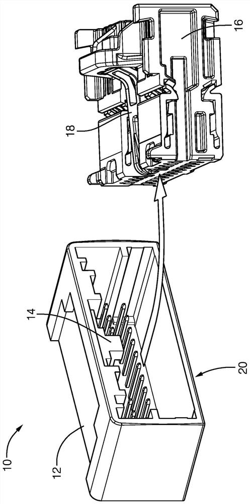
[0018] figure 1 is an exploded view showing the connector assembly 10 (hereinafter referred to as assembly 10). Assembly 10 includes a first connector 12 having locking lugs 14 and a second connector 16 configured to mate with first connector 12 . The first connector 12 and the second connector 16 are formed from a polymer dielectric material. The diel...


PUM

PropertyMeasurementUnit
First thicknessaaaaaaaaaa

Abstract

A connector assembly includes a first connector and a second connector. The first connector has locking lugs. The second connector has a cantilevered latch configured to slidably engage the locking lug. Cantilevered latches consist of a pair of parallel latch arms. The pair of parallel latch arms terminates in a first beam spanning the pair of parallel latch arms. The cantilevered latch also includes a second beam parallel to the first beam. The second beam is configured to releasably lock the locking lug when the first connector is mated with the second connector. The pair of parallel latch arms includes a rib extending beyond the bottom surface of each individual latch arm. When the first connector is moved from the unmated position to the mated position, the locking lug deflects the pair of parallel latch arms toward the outer surface of the second connector, whereby the rib contacts the outer surface and restrains the pair of parallel latch arms deflection.

Description

[0001] Cross References to Related Applications [0002] This application claims the benefit of priority to U.S. Patent Application No. 15 / 946,343, filed April 5, 2018. technical field [0003] The present disclosure generally relates to an electrical connector, and more particularly, to an electrical connector with a connector lock. Background technique [0004] The connector locks of prior art electrical connectors tend to fail during mating / unmating cycles, thereby exhibiting low cycle durability. [0005] Therefore, there is a need for improvements to prior art electrical connectors. Contents of the invention [0006] In view of the problems described above, the present application aims to provide an electrical connector assembly which has good mating / unmating cycle durability. [0007] According to one aspect of the present application, there is provided a connector assembly comprising: a first connector having a locking lug; and a second connector configured to mat...

Claims


Application Information

Patent Timeline
IPC IPC(8): H01R13/627
CPCH01R13/6278H01R13/6272H01R2107/00H01R13/639H01R13/6273H01R13/635
Inventor E·M·霍切瓦尔B·N·考德威尔C·A·马格雷夫
Owner DELPHI TECH INC
Why Eureka
Try Eureka